
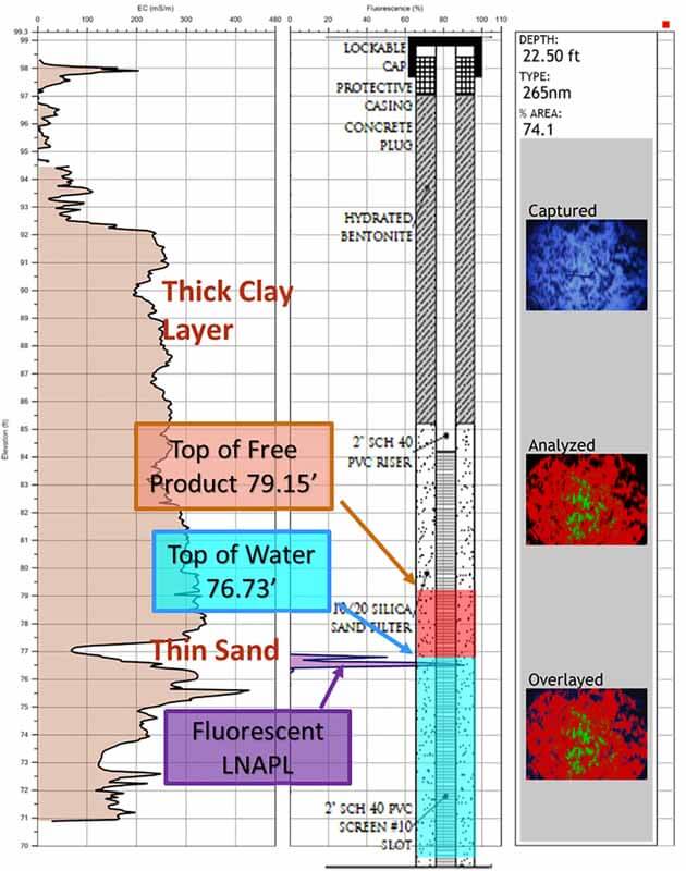
OIP-A07 reveals a thin LNAPL layer is confined under a thick clay (high conductivity) but gives a false or exaggerated thickness in monitor well DG-45
John Fontana, PG and President/CEO of Vista GeoScience in Golden, CO, and his direct sensing team are especially excited about the new Optical Image Profiler (OIP) system from Geoprobe Systems®.
“Geoprobe® released the OIP system in late 2016 and we added it to our tooling options soon after,” he said, “and the demand has kept it busy ever since. Our clients who have used other fuel fluorescence technologies on their sites are happy to see the OIP system produces very similar fluorescence responses and plume maps.” John says the 275nm excitation light responds very well even to the lightest hydrocarbons, including gasoline. “The saved fluorescence and visible images make this a very powerful system,” he added.
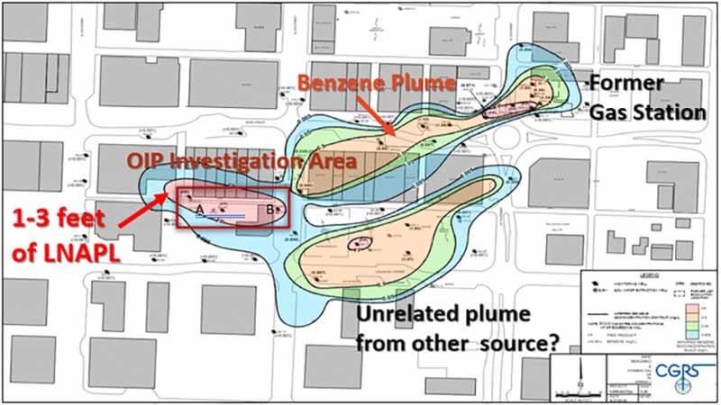
One of the first sites Vista GeoScience used the OIP system on was a state lead tank fund project in old downtown Grand Junction, CO, for CGRS Inc. Three of the site monitoring wells had 1 to 3 feet of gasoline LNAPL with a lead content dating back to the 1930s. The LNAPL is downgradient from a more recent release site and is believed to be from a different source area yet to be discovered. Their client wanted the investigation completed to expose the LNAPL migration pathway and determine the source of the product.
The investigation was conducted around two of the three monitoring wells that contained significant LNAPL. Several OIP borings detected LNAPL around the wells while others showed no LNAPL in as little as a 10-ft. step-out. The OIP logs provided some different explanations for the LNAPL thicknesses observed in the monitoring wells.
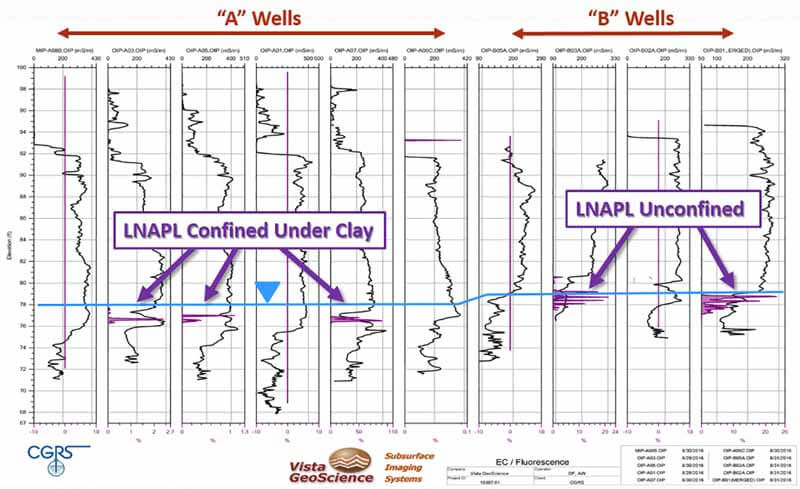
The LNAPL appears to be confined in a thin sand seam in the western area near DG-45 (A wells) and unconfined east near DG-28 (B wells). Groundwater flow is to the southwest; however, the slope of the confining clay layer could be allowing the LNAPL to migrate up gradient to the east where it becomes unconfined.
Additional borings are planned at this site to help determine if this is an accurate understanding of the plume migration.
“Mapping the LNAPL with OIP was crucial to understanding the intricacies of the geology and plume migration pathways of this site that has previously eluded the investigating consultants,” John added.
Contact Us
1835 Wall Street
Salina, Kansas 67401
Phone: (785) 825-1842
Photo Gallery
OIP-A07 reveals a thin LNAPL layer is confined under a thick clay (high conductivity) but gives a false or exaggerated thickness in monitor well DG-45
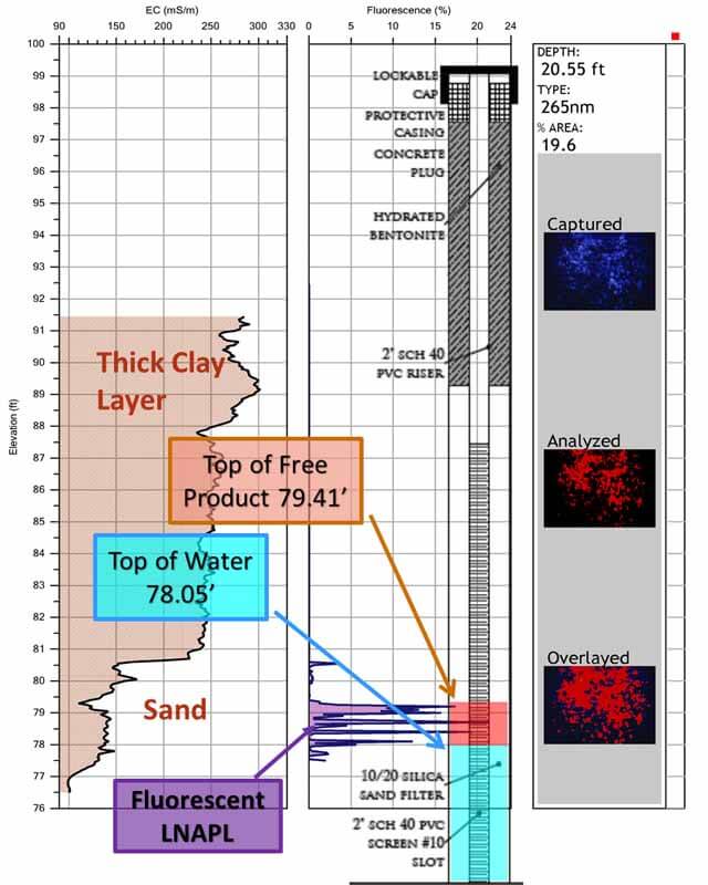
OIP-B03 reveals fluorescence over a thickness equivalent to the thickness in the nearby monitor well DG-28. This is because the LNAPL is no longer trapped by the confining clay as in A07.
The Grand Junction, CO, plume map.
OIP Log cross section with EC and OIP Fluorescence showing LNAPL under two different site conditions.
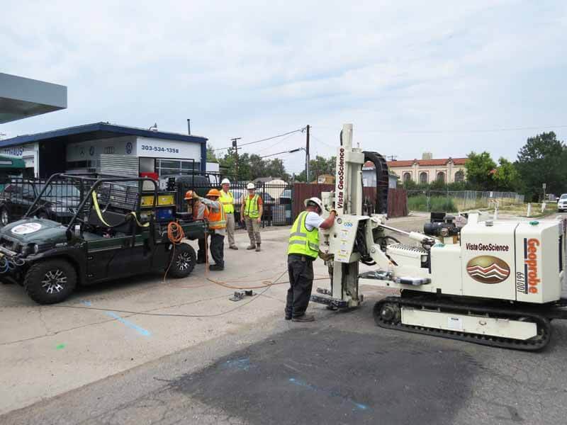
A Vista GeoScience field crew runs MIP (Membrane Interface Probe) and OIP (Optical Image Profiler) systems at a former gas station site in Denver, CO. Vista mounted their new MiHPT and OIP systems in a self-contained, steel pallet rack system which slides into the back of a 4WD ATV allowing maximum mobility and access on more difficult sites.
Related Videos
ID: 14050
ID: 6608
ID: 1997
ID: 1996
ID: 1994
ID: 1995
ID: 1979
ID: 1965
ID: 279