
Groundwater Sampling While Creating an HPT Pressure Log
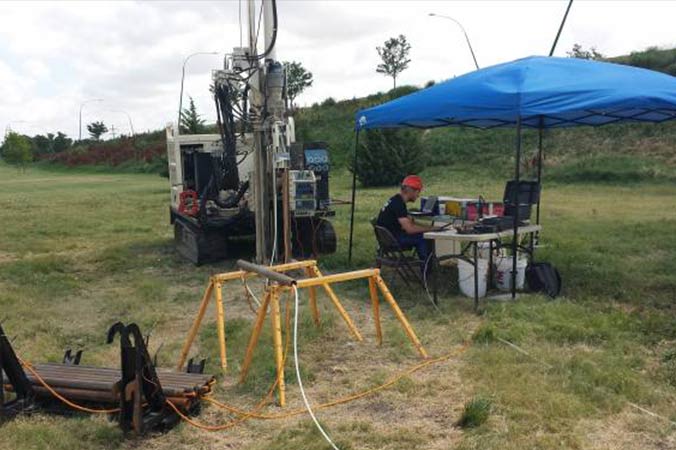
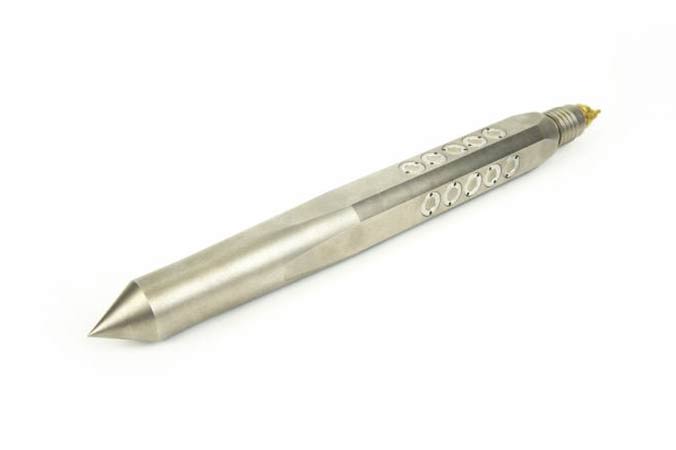
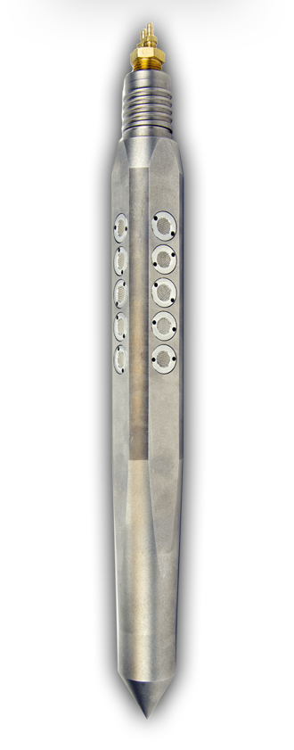
Groundwater profilers allow operators to create an injection pressure log utilizing the HPT (Hydraulic Profiling Tool) soil moisture probe instrumentation as well as stopping to sample groundwater in zones of high permeability. Vertically profile an aquifer and obtain numerous high-quality groundwater samples all while creating a injection pressure log. The groundwater profilers each have 20 HPT screens spread across 4.5in (11.4cm). They work well in highly permeable aquifers when numerous samples are desired.
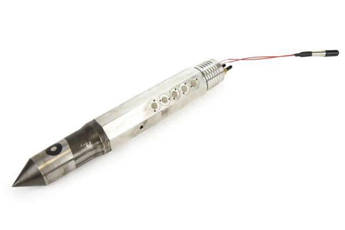
= Tool String Diagram (TSD)
GW Profiler Overview
What are the Geoprobe® Groundwater Profilers?
- Obtain logs of relative formation permeability.
- Logs HPT injection pressure, flow rates and electrical conductivity (HPT-GWS).
- Can stop during a log for groundwater sampling in high permeability zones.
- When using deionized water for the HPT injection and then switch for groundwater sampling, measure specific conductance of the sample to be confident you are sampling formation water.
- HPT-GWS can be used to map and sample brine plumes.
The groundwater profilers come in two sizes: 1.75in and 2.25in.
The GWP1.75 operates on 1.75in rods allowing you to record injection pressure at the surface for formation permeability, so you understand the zones with the highest permeability which will provide the best opportunity to obtain groundwater samples. This tool does not use a downhole pressure transducer or an electrical conductivity dipole.
The HPT-GWS operates on 2.25in rods and will result in very similar HPT style logs. This tool allows room to include the electrical conductivity dipole and wiring as well as using a downhole HPT pressure transducer. The logs are nearly identical to traditionally run HPT logs including EC, downhole HPT pressure and the ability to determine static water level. The calculations for estimated K are not accurate since the Estimated K model was not designed for a 20-screen probe. This probe will also help determine the zones of highest permeability for good quality groundwater sampling during the generation of the HPT log.
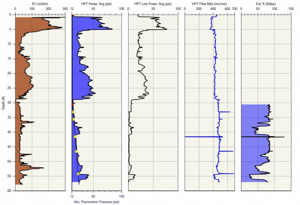
HPT-GWS Log:
The Yellow triangles on the Piezometric Graph are Dissipation Tests and Groundwater Sample Locations
Groundwater Sampling:
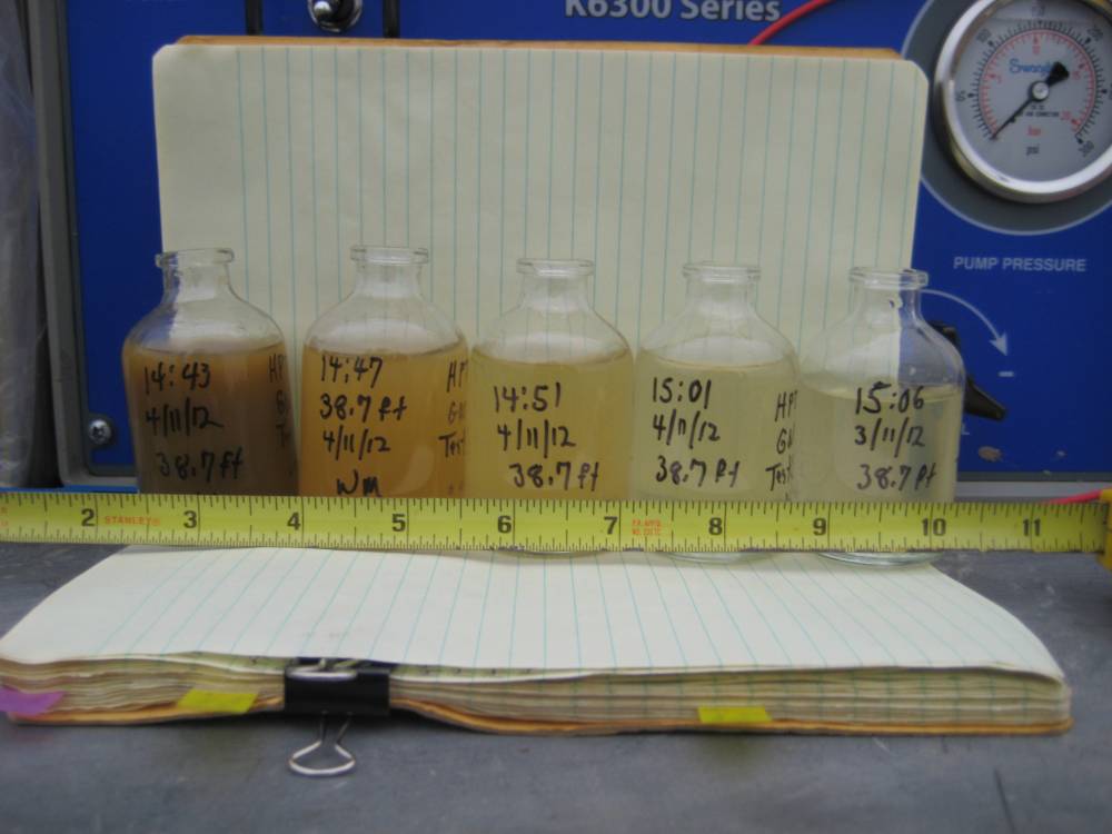
The reduction in suspended solids in the groundwater samples over time
Principles Of Operation
While the probe is advanced, the operator will inject deionized water which has very low specific conductance values. An injection pressure log is created and the operator can watch for depths below the known groundwater table where there is very low injection pressure thus a zone of high permeability. To collect a groundwater sample the probe advancement is stopped, the DI acquisition software will be switched from the depth to time graph and a dissipation test will be started. The operator will shut off the HPT pump and the mechanical actuator can be placed on top of the rods. After mounting the groundwater sampling tubing within the actuator, the actuator can be started. Water will eventually be drawn out of the sample tubing and then the user can monitor the specific conductance values of the water. Initially the DI water used to inject with will show very low specific conductance, as more formation water reaches the surface the specific conductance values will rise and eventually stabilize. At this point the operator can be confident that formation groundwater will be sampled.
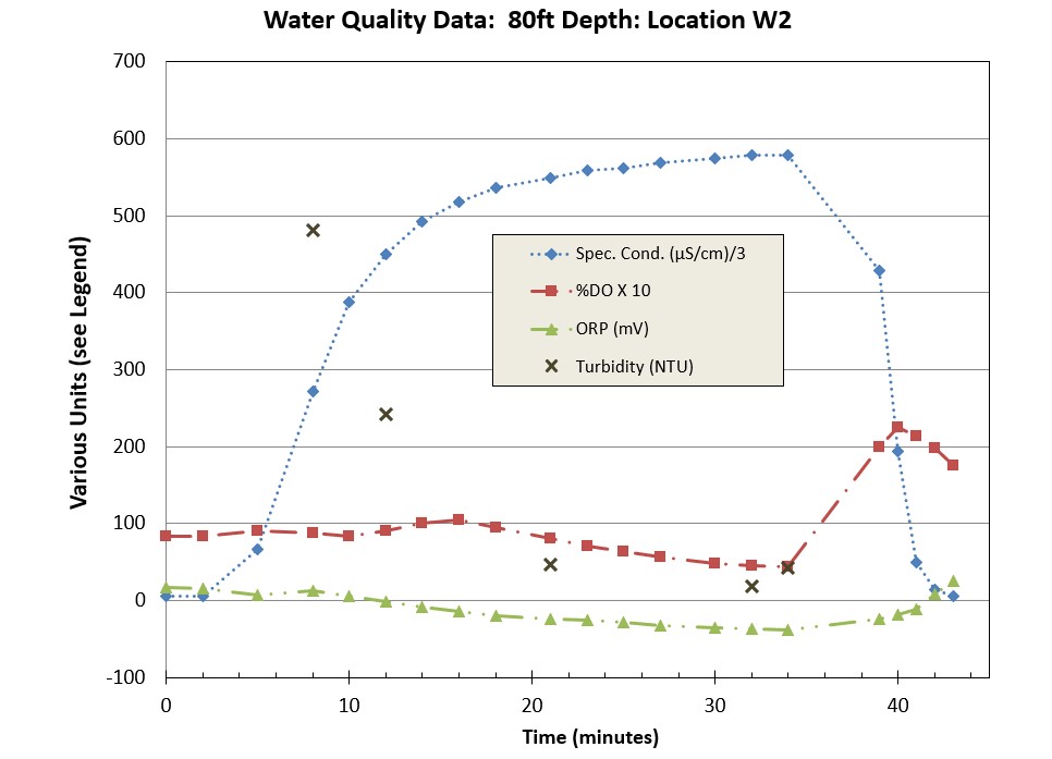
We encourage the injection of deionized water with these tools which has extremely low specific conductance values. These values are significantly higher in formation water than the DI water and when the user monitors the specific conductance of the sampled water they can have great confidence when the sample water has stabilized into formation water. In the graph below we see how the specific conductance values are low as the injected DI water is purged from the sample line. As the DI water is replaced with the formation water the specific conductance values increase drastically until they stabilize which is where samples will be collected for lab analysis.
Water Quality Parameters:
Recording of water quality parameters during a groundwater sampling event
After completing the groundwater sampling, the HPT injection pump will be restarted and pumping will continue. A greater flow of water is injected than is sampled so the operator will inject DI water while at the same time wash out the probe and sample tubing replacing the formation water with the DI water before advancing to the next sample location. This is considered the tool cleanup process which is seen as the rapid drop in specific conductance of the sampled water after 35minutes in the above graph. System blanks or check samples can be taken at this point and then the log continued until the next sampling location.
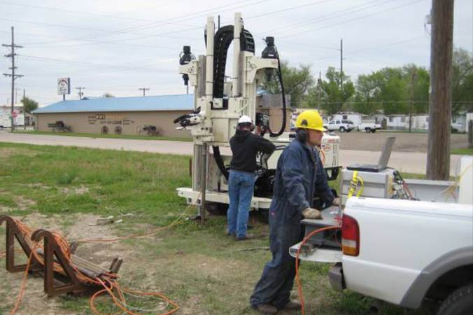
Pumps Used With GW Profilers
Depending upon the purpose of the groundwater sampling and the depth to groundwater the operator may choose from a variety of pump options.
There are two downhole pump options: the mechanical syringe pump (MSP) and the mechanical bladder pump (MBP). Both were developed by Geoprobe® engineers and would be required when the depth to groundwater exceeds 25 ft (7.5m) bgs. The MSP tends to perform better than the MBP when the number of samples taken in a borehole exceeds five as there are fewer wear components that can break during the log. The MSP is also preferential when sampling for PFAS compounds since there are no Teflon® components within this pump system. The syringe pump does tend to pull a larger vacuum on the sample which may lead to the degassing of some volatile analytes from the sample.
The MBP may be more desirable when sampling for VOCs and taking four or fewer samples within the boring. Bladder pumps apply the least amount of vacuum on a sample thus are least likely to strip out any volatile analytes from the sample. The bladder, made of either corrugated Teflon® or polyethylene, should work fine for this number of samples. Bladder pumps are also the best choice of pump for low flow VOC sampling as listed by the US EPA in their low flow groundwater sampling procedures document.
https://www.epa.gov/sites/production/files/2015-06/documents/lwflw2a.pdf
An alternative pump that can be used with the groundwater profiler would be a peristaltic pump when the depth to groundwater is less than 25ft (7.5m) bgs. When using a peristaltic pump an operator would insert the sample line tubing directly to one of the barbs in the top of the groundwater profiler and when it comes time to collect the groundwater sample, the HPT pump is shut off and the peristaltic pump is started bringing the groundwater sample to the surface. Peristaltic pumps also can apply a vacuum to the sample which can cause degassing and strip VOC analytes from the groundwater sample.
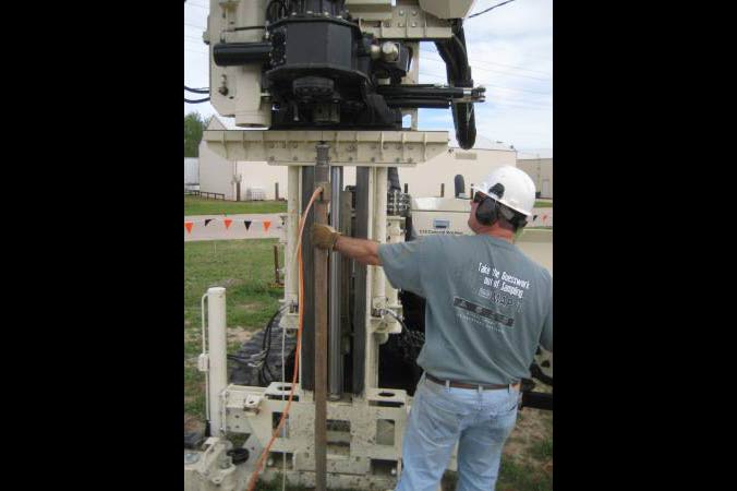
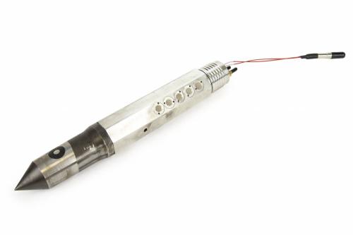
MBP/MSP Electric Actuator
When using either the mechanical bladder or syringe pump the operator will want to use the electric actuator to work the downhole pump. The electric actuator can be mounted on any 1.75in or 2.25in probe rods to actuate the sample line and downhole pump allowing the user to focus on preparing sample bottles and monitoring the purge water for specific conductance to verify that formation water is being collected.
Electric Actuator:
Collecting groundwater samples from the MSP
Features & Options
HPT-GWS
What are the Geoprobe® Groundwater Profilers?
- Obtain logs of relative formation permeability.
- Logs HPT injection pressure, flow rates and electrical conductivity (HPT-GWS).
- Can stop during a log for groundwater sampling in high permeability zones.
- When using deionized water for the HPT injection and then switch for groundwater sampling, measure specific conductance of the sample to be confident you are sampling formation water.
- HPT-GWS can be used to map and sample brine plumes.
The groundwater profilers come in two sizes: 1.75in and 2.25in.
The GWP1.75 operates on 1.75in rods allowing you to record injection pressure at the surface for formation permeability, so you understand the zones with the highest permeability which will provide the best opportunity to obtain groundwater samples. This tool does not use a downhole pressure transducer or an electrical conductivity dipole.
The HPT-GWS operates on 2.25in rods and will result in very similar HPT style logs. This tool allows room to include the electrical conductivity dipole and wiring as well as using a downhole HPT pressure transducer. The logs are nearly identical to traditionally run HPT logs including EC, downhole HPT pressure and the ability to determine static water level. The calculations for estimated K are not accurate since the Estimated K model was not designed for a 20-screen probe. This probe will also help determine the zones of highest permeability for good quality groundwater sampling during the generation of the HPT log.
HPT-GWS Log:
The Yellow triangles on the Piezometric Graph are Dissipation Tests and Groundwater Sample Locations
Groundwater Sampling:
The reduction in suspended solids in the groundwater samples over time
While the probe is advanced, the operator will inject deionized water which has very low specific conductance values. An injection pressure log is created and the operator can watch for depths below the known groundwater table where there is very low injection pressure thus a zone of high permeability. To collect a groundwater sample the probe advancement is stopped, the DI acquisition software will be switched from the depth to time graph and a dissipation test will be started. The operator will shut off the HPT pump and the mechanical actuator can be placed on top of the rods. After mounting the groundwater sampling tubing within the actuator, the actuator can be started. Water will eventually be drawn out of the sample tubing and then the user can monitor the specific conductance values of the water. Initially the DI water used to inject with will show very low specific conductance, as more formation water reaches the surface the specific conductance values will rise and eventually stabilize. At this point the operator can be confident that formation groundwater will be sampled.
We encourage the injection of deionized water with these tools which has extremely low specific conductance values. These values are significantly higher in formation water than the DI water and when the user monitors the specific conductance of the sampled water they can have great confidence when the sample water has stabilized into formation water. In the graph below we see how the specific conductance values are low as the injected DI water is purged from the sample line. As the DI water is replaced with the formation water the specific conductance values increase drastically until they stabilize which is where samples will be collected for lab analysis.
Water Quality Parameters:
Recording of water quality parameters during a groundwater sampling event
After completing the groundwater sampling, the HPT injection pump will be restarted and pumping will continue. A greater flow of water is injected than is sampled so the operator will inject DI water while at the same time wash out the probe and sample tubing replacing the formation water with the DI water before advancing to the next sample location. This is considered the tool cleanup process which is seen as the rapid drop in specific conductance of the sampled water after 35minutes in the above graph. System blanks or check samples can be taken at this point and then the log continued until the next sampling location.
Depending upon the purpose of the groundwater sampling and the depth to groundwater the operator may choose from a variety of pump options.
There are two downhole pump options: the mechanical syringe pump (MSP) and the mechanical bladder pump (MBP). Both were developed by Geoprobe® engineers and would be required when the depth to groundwater exceeds 25 ft (7.5m) bgs. The MSP tends to perform better than the MBP when the number of samples taken in a borehole exceeds five as there are fewer wear components that can break during the log. The MSP is also preferential when sampling for PFAS compounds since there are no Teflon® components within this pump system. The syringe pump does tend to pull a larger vacuum on the sample which may lead to the degassing of some volatile analytes from the sample.
The MBP may be more desirable when sampling for VOCs and taking four or fewer samples within the boring. Bladder pumps apply the least amount of vacuum on a sample thus are least likely to strip out any volatile analytes from the sample. The bladder, made of either corrugated Teflon® or polyethylene, should work fine for this number of samples. Bladder pumps are also the best choice of pump for low flow VOC sampling as listed by the US EPA in their low flow groundwater sampling procedures document.
https://www.epa.gov/sites/production/files/2015-06/documents/lwflw2a.pdf
An alternative pump that can be used with the groundwater profiler would be a peristaltic pump when the depth to groundwater is less than 25ft (7.5m) bgs. When using a peristaltic pump an operator would insert the sample line tubing directly to one of the barbs in the top of the groundwater profiler and when it comes time to collect the groundwater sample, the HPT pump is shut off and the peristaltic pump is started bringing the groundwater sample to the surface. Peristaltic pumps also can apply a vacuum to the sample which can cause degassing and strip VOC analytes from the groundwater sample.
When using either the mechanical bladder or syringe pump the operator will want to use the electric actuator to work the downhole pump. The electric actuator can be mounted on any 1.75in or 2.25in probe rods to actuate the sample line and downhole pump allowing the user to focus on preparing sample bottles and monitoring the purge water for specific conductance to verify that formation water is being collected.
Electric Actuator:
Collecting groundwater samples from the MSP
Videos
ID: 1954
Resources
Click on a section below to view information.

Direct Image® Tooling provides high-quality data in the unforgiving geology of Alaska.
ID: 14360 | Date:
Leaning on the can-do lessons of his Marine training and the small-company culture he cherished during his first drilling job guides building Veteran Drilling into high resolution site characterization resource for California.
ID: 5775 | Date:
Depend on Team Geoprobe®
Since 1987, Geoprobe® has manufactured innovative drilling rigs and tooling - engineered for efficiency and safety - simplifying drillers’ jobs and empowering their companies to succeed as productive and profitable leaders in the industry. When you partner with Geoprobe® you receive:
Customer-inspired Innovation
Engineering and building industry-leading drilling rigs, tooling, and techniques for the technical driller based on your needs to work safer and more efficiently.
Exceptional Value
Ensuring drilling rigs and tooling are created in conjunction – with consistent quality – to collect the highest-quality information with the most accurate result to get you to, into, and through the job efficiently.
Superior Service
Equipping you to do your best job and keeping you in the field via one-on-one expert sales and service technicians manning live support phone lines, shipping necessary parts same-day.
What are the Geoprobe® Groundwater Profilers?
- Obtain logs of relative formation permeability.
- Logs HPT injection pressure, flow rates and electrical conductivity (HPT-GWS).
- Can stop during a log for groundwater sampling in high permeability zones.
- When using deionized water for the HPT injection and then switch for groundwater sampling, measure specific conductance of the sample to be confident you are sampling formation water.
- HPT-GWS can be used to map and sample brine plumes.
The groundwater profilers come in two sizes: 1.75in and 2.25in.
The GWP1.75 operates on 1.75in rods allowing you to record injection pressure at the surface for formation permeability, so you understand the zones with the highest permeability which will provide the best opportunity to obtain groundwater samples. This tool does not use a downhole pressure transducer or an electrical conductivity dipole.
The HPT-GWS operates on 2.25in rods and will result in very similar HPT style logs. This tool allows room to include the electrical conductivity dipole and wiring as well as using a downhole HPT pressure transducer. The logs are nearly identical to traditionally run HPT logs including EC, downhole HPT pressure and the ability to determine static water level. The calculations for estimated K are not accurate since the Estimated K model was not designed for a 20-screen probe. This probe will also help determine the zones of highest permeability for good quality groundwater sampling during the generation of the HPT log.
HPT-GWS Log: The Yellow triangles on the Piezometric Graph are Dissipation Tests and Groundwater Sample Locations
Groundwater Sampling: The reduction in suspended solids in the groundwater samples over time
:
:
While the probe is advanced, the operator will inject deionized water which has very low specific conductance values. An injection pressure log is created and the operator can watch for depths below the known groundwater table where there is very low injection pressure thus a zone of high permeability. To collect a groundwater sample the probe advancement is stopped, the DI acquisition software will be switched from the depth to time graph and a dissipation test will be started. The operator will shut off the HPT pump and the mechanical actuator can be placed on top of the rods. After mounting the groundwater sampling tubing within the actuator, the actuator can be started. Water will eventually be drawn out of the sample tubing and then the user can monitor the specific conductance values of the water. Initially the DI water used to inject with will show very low specific conductance, as more formation water reaches the surface the specific conductance values will rise and eventually stabilize. At this point the operator can be confident that formation groundwater will be sampled.
We encourage the injection of deionized water with these tools which has extremely low specific conductance values. These values are significantly higher in formation water than the DI water and when the user monitors the specific conductance of the sampled water they can have great confidence when the sample water has stabilized into formation water. In the graph below we see how the specific conductance values are low as the injected DI water is purged from the sample line. As the DI water is replaced with the formation water the specific conductance values increase drastically until they stabilize which is where samples will be collected for lab analysis.
Water Quality Parameters: Recording of water quality parameters during a groundwater sampling event
After completing the groundwater sampling, the HPT injection pump will be restarted and pumping will continue. A greater flow of water is injected than is sampled so the operator will inject DI water while at the same time wash out the probe and sample tubing replacing the formation water with the DI water before advancing to the next sample location. This is considered the tool cleanup process which is seen as the rapid drop in specific conductance of the sampled water after 35minutes in the above graph. System blanks or check samples can be taken at this point and then the log continued until the next sampling location.
:
:
:
When using either the mechanical bladder or syringe pump the operator will want to use the electric actuator to work the downhole pump. The electric actuator can be mounted on any 1.75in or 2.25in probe rods to actuate the sample line and downhole pump allowing the user to focus on preparing sample bottles and monitoring the purge water for specific conductance to verify that formation water is being collected.
Electric Actuator: Collecting groundwater samples from the MSP
:
:
: