
A few years back, the Nebraska Department of Health and Human Services began testing all of the water supply wells across Nebraska to be sure they were in compliance with the new uranium-mass regulation promulgated by the U.S. EPA. This new regulation established a maximum contaminant level (MCL) of 30 ug/L for uranium in drinking water. Tom Christopherson, Program Manager for Water Well Standards of DHHS, soon learned that the old public water supply (PWS) wells in the small farming community of Clarks in central Nebraska were contaminated with uranium at concentrations between 100 to 200 ug/L. This was bad news for the approximately 375 residents of Clarks. After a difficult search, they installed two test wells about 1.5 miles northeast of town, and both wells were nondetect for uranium. Two new PWS wells were installed adjacent to the test wells, and initial pumping and testing found that the new North well was yielding water with uranium concentrations about 30 ug/L. After initial testing was done by the University of Nebraska - Lincoln, it became apparent that a modified, low-speed pumping program was not going to correct the problem. It was then that Tom Christopherson asked if Geoprobe Systems® would demonstrate direct push methods at the site, and assist the agency in understanding the cause of the elevated uranium problem at the Clarks well field.
Geoprobe® R&D Team Mobilizes
Led by Wes McCall, Geoprobe® Environmental Geologist, a team of Geoprobe® Research and Development Engineers mobilized equipment to Clarks in September and performed a 4-day expedited investigation at the new well field. According to Wes, “Going to sites such as this allows the Geoprobe® R&D team to test new techniques and tooling in ‘real world’ applications. Not only was this a great site to test our new tooling, but we were also able to help a small community in need of safe drinking water.”
A Look Below the Surface: HPT Logging Begins
Using the Hydraulic Profiling Tool (HPT), five HPT logs were collected across the well field site. A Geoprobe® 6625CPT machine and the HPT system were used to gather information on the local hydrostratigraphy at depths approaching 120 feet. The first log (HPT1) was obtained near the South Public Water Supply (PWS) well. “HPT logs allowed us to ‘see’ subsurface information,” Wes explained, “and helped us to plan the placement of monitoring wells during the next steps in the project.” The logs revealed the presence of several fine-grained layers or lenses separating thicker sand zones. Also shown on the first log (next page) is the construction of the 4-inch diameter test well and the new 12-inch diameter South PWS well, based on drillers’ logs. The North PWS well and test well were constructed similarly.
A Look At the Groundwater: DP Monitoring Wells Installed
On Day Two, another team arrived for monitoring well installation using direct push (DP) methods. “Based on the information displayed in the HPT logs,” Wes said, “0.75-in. ID prepacked screen wells were installed at selected depths adjacent to the HPT1 log location (A-Group wells).” Five-foot prepacks were installed in the aquifer between the fine-grained lenses which were identified by the HPT logs.
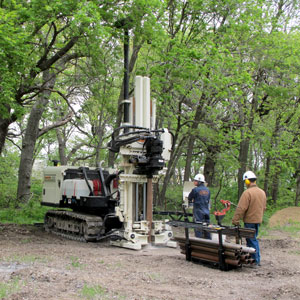
During this process, the R&D team used the new Model 8040DT machine to advance 2.25 in. OD rods up to 118-feet deep. A new Model GS2250 grout machine performed bottom-up tremie grouting with a 25 percent solids bentonite slurry. A second set of prepacked screen wells (B-Group) was installed beside the HPT2 location and at some distance from both of the PWS wells. Because of the 8040DT’s capabilities, eight of the prepacked wells were installed in two days. The fifth shallow well at HPT2 was installed the following morning.
A Look At the Groundwater: Sampling the Wells
One-half-inch PE tubing and tubing bottom check valves were used for the initial development of the 0.75-in. prepacked screen wells. The 12-volt Geoprobe® Electric Actuator powered the check valve system to develop the wells up to 115 ft. deep. The check valves were moved across the screen interval to surge and purge between five and twenty gallons from each well. After the initial development significantly lowered the turbidity, mechanical bladder pumps were installed to perform low-flow purging and sampling. Electric actuators also powered the bladder pumps at flow rates between approximately 150 ml/min to 300 ml/min. Flow from the pumps was directed through a small flow cell equipped with a YSI556 Multi-Parameter Probe to monitor water quality parameters (DO, ORP, pH, Specific conductance and temperature). Turbidity was monitored periodically with a Cole Parmer turbidity meter. Turbidity was below 10 (NTU) in all of the wells prior to sampling. DHHS personnel collected samples for several cations, anions, and trace elements, including uranium, from each of the newly-installed prepacked screen wells. “Since one of the 4-in. test wells had shown elevated uranium from earlier sampling,” Wes said, “both of these wells were sampled for all of the analytes and uranium using mechanical bladder pumps and the electric actuators.”
Samples from all nine of the DP installed prepacked screen wells and the two 4-in. test wells were collected by DHHS personnel and submitted to the Nebraska State Laboratory for analysis. According to a brief summary of the chemistry for the A-Group wells, which were installed near the South PWS well, the Specific conductance, sodium (Na), sulfate (SO4), selemium (Se) and uranium (U) all tended to decrease with depth. Wes explained, “However, the results for the South 4-in. test well, near the A-Group DP wells, appeared anomalous. Although the test well was screened deep in the aquifer, it had chemistry similar to the shallow DP wells (A4 & A3), and was out of equilibrium with the deep DP wells (A1 & A2) screened at similar depths. Based on HPT log information and well data, the gravel packed annulus of the old 4-in. test well was behaving as a conduit for shallow groundwater to move down to depth in the aquifer, especially when the PWS well pumps were activated.” Probably most obvious is the uranium in the South 4-in. test well. “Data indicates that the uranium levels in the South test well are 168 ug/L, which is about five times higher than anything observed in the nearby A-Group wells for uranium,” Wes added. “This is definitely not in equilibrium with the A1 and A2 DP wells screened at similar depths, which are both non-detect for uranium.”
Results for the B-Group wells show that Specific conductance, Na, SO4, and Se again tend to decrease with depth. However, uranium concentrations are distinctly higher in the B4 and B3 wells ... up to 376 ug/L. According to Wes, “It appears that these two zones in the aquifer are probable sources for the uranium observed in the South 4-in. test well and the PWS wells.” By observing the construction information of the South PWS well, the filter pack extends up to approximately 60 ft. below grade. This means that the filter pack for this well directly intersects the B3 zone of the aquifer with the high uranium concentrations. “It becomes apparent,” he said, “that both the filter-packed annulus of the original test wells and the extended filter pack of the PWS wells allow for movement of groundwater from shallow zones of the aquifer downward into the well screen.”
Project Success Takes The Right Equipment
It’s important to note that all of the field investigation activities described here took place in less than a week on-site. That’s nine prepacks set to depths up to 110 feet for a total of 609 feet of prepack installation.
“This was a good project to demonstrate the ability of the new 8040DT machine,” noted Tom Christy, Geoprobe® Vice President. “The installations went faster and smoother than anything we could have achieved with our other model probe machines.”
Tom also noted that this project sets a good example for the use of direct push logging data. “We sent the HPT unit out there a day ahead of time. The logs we got were very informative; showing us clay and fine-grained zones that previous investigations of the site by drilling just were not able to pick up. We knew exactly where to set our prepacks to get a good, multi-level picture of the distribution of uranium. As a result, all of the prepacks developed and yielded good samples for analysis.
Based on knowledge of the geology, the contamination is not caused by human activity but rather the uranium occurs naturally in the sediments of the aquifer. There is also some uranium in the soil outside your window and in the soil most everywhere on the planet. And actually the U in the soil outside your window may be 10 to 100 times the concentration in the drinking water the people in the community of Clarks were drinking, Wes explained.
Ultimately, the uranium in the aquifer sediments below Clarks comes from the sedimentary rocks in eastern Wyoming and also from the granites in the rocky mountains. The rivers erode the sedimentary rocks and granites, and carry the sand, silt, clay, and gravels down the Platte River ... along with the uranium inside of them. These sediments now make up the aquifer materials in the Platte River and Village of Clarks water supply aquifer.
According to Wes, the real problem is exposure to the uranium. “We don’t eat the soil, and we usually don’t put your dirty hands in your mouth,” he said. “We usually don’t inhale much of it either, even on dry windy days in the central plains. So we don’t actually get ‘exposed’.”
Unfortunately for the people in Clarks, the small amount of uranium in the sediments in their aquifer (probably only a few parts per million) is dissolving a little in the groundwater due to the groundwater chemistry in some parts of the aquifer. This dissolved uranium gets pulled in by the pump in their supply wells and it gets to their water tap at home. “The residents of Clark drink the water or cook with the water,” Wes said, “and so ingest it and are ‘exposed’. It seems the primary concern with uranium is not its radioactive decay in the body (though that’s not good), but the effects Uuranium has on our kidneys as a heavy metal causing damage to the organ.”
The Next Step
Currently, the community of Clarks is having the test wells properly abandoned and is evaluating corrective measures for the new PWS wells to come back into compliance with the 30 ug/L uranium MCL.
Wes concluded, “While we’re more familiar investigating problems with man-made contaminants, like gasoline or TCE in our aquifers, this project demonstrates that naturally-occurring materials, such as uranium or arsenic, can be a significant problem.” He also stated that this project revealed that the same direct push methods the industry has applied for the investigation of other contaminants works well to understand the presence and distribution of naturally occurring analytes. “It’s easy to imagine how differently the PWS well design and construction would have progressed,” Wes concluded, “if the data from the small DP wells had been available before the project was started.”
Helping the Industry and the Environment
Although finding uranium in your drinking water isn’t good news for the people in Clarks, having the ability to test new products on sites such as this is beneficial to the Geoprobe® R&D team. It also has a positive impact on the industry. New technology and product improvements to better the environment are a direct result of being able to test equipment and new ideas. It’s also a good reminder of why the direct push method is good for both the environment and for those who work in this industry. Although the levels of uranium were high in the groundwater, at no time was the site team exposed to contaminants or were there hazards to their safety. There were no waste cuttings generated at the site which eliminated the need for handling, storage, sampling, analyzing, transporting, or disposing of the contaminated waste ... both a risk to health and a costly investment.
Additional information about this investigation and the specific field methods applied and equipment used is available by contacting Wes McCall at Geoprobe Systems®, 1-800-436-7762 or at mccallw@geoprobe.com.
Contact Us
1835 Wall Street
Salina, Kansas 67401
Phone: (785) 825-1842
Related Videos
ID: 1918
ID: 1960
ID: 1991
ID: 1992
ID: 1954
ID: 1965
ID: 279