
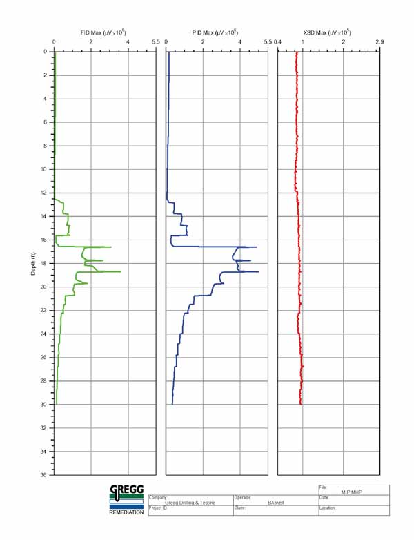
MIP data is displayed by plotting the three individual detector responses with depth.
Gregg Drilling & Testing, based in California, recently partnered with a Northern California environmental consultant to provide Membrane Interface Probe (MIP) and Cone Penetration Testing (CPT) services to aid in delineating the extent of a contamination plume. Previously, the consultant has relied on traditional monitoring well data to define the plume, but felt using the MIP and CPT would provide more refined data which would save money on In-Situ Chemical Oxidation (ISCO) costs in the future.
Todd Hanna, Remediation Program Manager, said the combined CPT and MIP systems offered cost-effective and rapid screening capabilities. “Pairing these two systems emerged as the best tool for screening the groundwater impacted zones to define vertical and horizontal extent of the plume,” he said.
The site was a fuel storage facility utilizing underground tanks, and remained in use until 1990. The focus of the investigation was delineating a plume of TPH-g (Total Petroleum Hydrocarbons – Gasoline) with a possibility of encountering diesel hydrocarbons as well. ”Our goal was to implement a strategy to remediate the site using ISCO so the client could eventually sell the property,” Todd added.
Gregg Remediation used an MIP system with a PID, XSD and FID coupled with CPT tooling. These tools gather the soil stratigraphy, groundwater information and contaminant screening with depth. The company was tasked to collect 15 boring locations to depths of approximately 30-feet below ground surface.
Frank Stolfi, HRSC Division Manager explained the process. “Raw data was collected from the MIP showing a spike in all three detectors from roughly 12- to 24-feet in depth,” he said. “Because the CPT and MIP are pushed as one unit, soil cuttings are eliminated and we completed the entire site investigation quickly, achieving roughly 200-ft. per day.
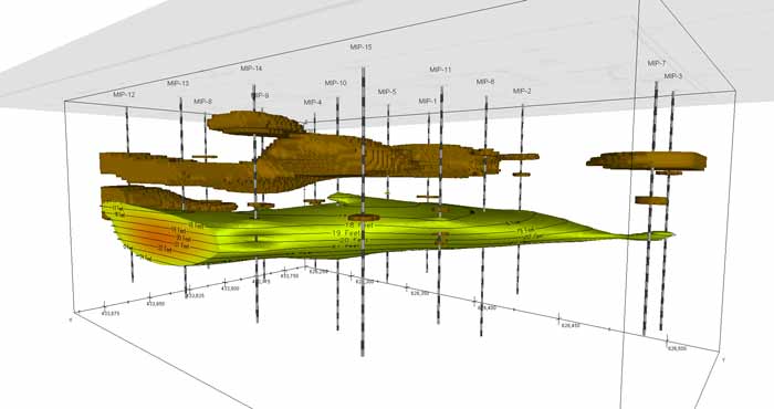
Using the Earth Volumetric Software by CTech, Frank created a 3D image of the plume for visualization purposes. The PID detector data, in combination with the CPT data, showed a silt layer on-site. “The visualization aids consultants with demonstrating the extent of the plume to their client,” Frank said, “as well as designing an appropriate ISCO solution to target the specific plume. Adding in the soil stratigraphy aids in determining the proper remediation solution when considering permeability of certain layers and the soil type containing the hydrocarbons.”
Gregg Remediation, a division within Gregg Drilling and Testing Inc., a California-based site investigation contractor, provides HRSC (High Resolution Site Characterization) tooling and chemical injection for remedial approaches.
Contact Us
1835 Wall Street
Salina, Kansas 67401
Phone: (785) 825-1842
Photo Gallery
MIP data is displayed by plotting the three individual detector responses with depth.
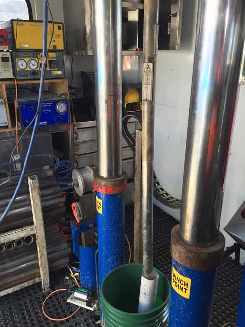
MIP and CPT tooling ready for deployment.
3D Model of the PID detector above a threshold of 1.0E+6 and CPT data (silty soil)..
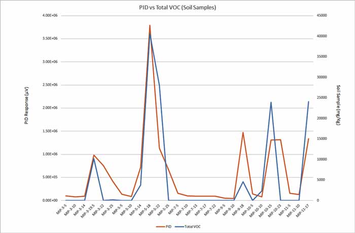
Comparison of PID response to discrete soil sample total response.
Related Videos
ID: 6608
ID: 6082
ID: 5344
ID: 1975
ID: 1892
ID: 1995
ID: 1979
ID: 1977