
Wes McCall
So most, if not all of you, are familiar with conventional pneumatic bladder pumps. You know ... a generator to run the compressor, a pump controller to regulate the air flow from the compressor to operate the pump downhole ... lines, cables, tubing, hoses, noises, leaks ... ugh! All this so the compressed air can squeeze a small Teflon® bladder to push water slowly up a small tube to the surface. Just how many horsepower are used to pump that water to the surface so we can collect two 40 mL vials for VOC analysis? Amazing inefficiency, isn’t it? While the mechanical bladder pump still uses a bladder, it operates a little differently ... but more efficiently.
What is the Mechanical Bladder Pump? How Does A Bladder Pump Work?
To answer part of this question just remember you don’t need a generator, a compressor, or a pneumatic pump controller to operate it. The mechanical bladder pump (MBP) is very simple. It has about a dozen parts and uses a corrugated Teflon® bladder. A set of concentric tubes extends from the top of the pump to the surface. The outer tube (HDPE) threads directly into the body of the pump and the inner tube (usually FEP Teflon®) threads onto an adapter that connects to the corrugated bladder. At the surface, the outer tube is held in place while the inner tube is alternately raised and lowered about four inches (100 mm). This alternately raises (expands) and lowers (compresses) the corrugated bladder. There are check balls above and below the bladder which regulate fluid movement up the inner tube to the surface. A spring above the bladder helps to compress it and pull the inner tube back down during the sample stroke (as the engineers say “it’s hard to push a string”).
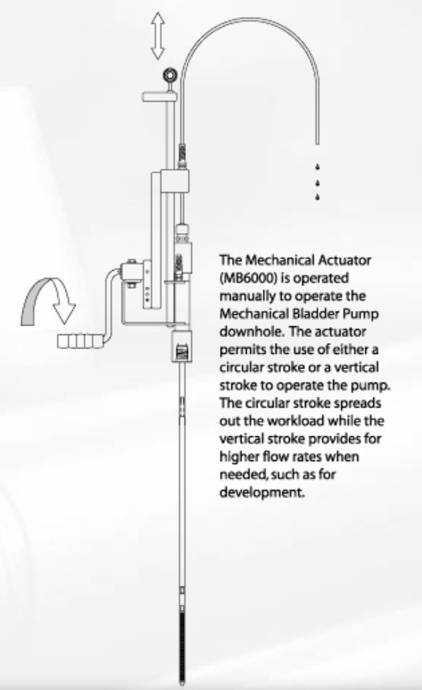
Now you ask, “Do I actually hold the outer and inner tubes with my hands to operate the pump?”. You can do it that way. It’s tedious but it definitely works. Another option is a simple set of hand grips (Manual Actuator Kit, MB7000) that fits on the inner and outer tubes to make holding them easier. The manual actuator makes it easy on your hands and also on your bank account! If you’re going to be pumping for more than 10 or 15 minutes per sample, you may want to consider the Mechanical Actuator (MB6000). It can be mounted on your probe rods or conventional PVC casing up to nominal two-inch (50 mm) diameter. The actuator has a poly compression fitting that holds the outer tube in place and another that holds the inner tube to the slider block and arm. The crank arm on the MB6000 can be used to operate the pump using a circular stroke. The pump is easy and comfortable to operate with the circular stroke and can provide flow rates of up to several hundred milliliters per minute. The mechanical actuator can also be operated with a vertical stroke.
How About Flow Rates?
Next question ... what about flow rates? No, you will not get five gallons of water per minute from this little pump (remember, it’s less than 0.5 inch [only 12 mm]) in diameter. But when compared to other same-sized bladder pumps, you can get good flow rates.
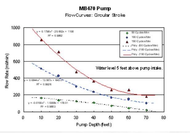
Earlier this spring I installed a closed stand pipe to a depth of 70 feet (21.3 m) so we could conduct some flow tests with the MB470. A series of tests were conducted as the pump was lowered on 10-foot (3 m) increments and the water level was maintained 5 feet (1.5 m) above the pump intake during each test in the stand pipe. A peristaltic pump was used to add water during the flow tests to maintain the correct water level. Using the mechanical actuator with circular strokes, the maximum flow rate achieved was almost 850 mL/min with the pump intake at 10 feet, water level at 5 feet, and pump speed of 150 cycles per minute (shown in the graph on the right). When a vertical stroke was used to actuate the pump under the same conditions, the maximum flow rate approached 950 mL/min. The flow rates that can be obtained are very useful for the low-flow minimal drawdown sampling protocol recommended by the U.S. EPA and many state regulatory agencies for water quality sampling. Even with the pump intake at 70 feet and water level at 65 feet, you can get a flow rate around 100 mL/min with a circular stroke at 100 cycles per minute ... not bad for low-flow protocol in small wells.
Last, But Definitely Not Least, What About Sample Quality?
Obviously, for environmental investigations of groundwater contamination, getting representative samples is an absolute must. So we went directly to the U.S. EPA for help in evaluating the sample quality obtained from the Mechanical Bladder Pump. The EPA’s Environmental Technology Verification (ETV) Program was planning a verification study of small diameter groundwater sampling devices that could be used in small diameter wells. Geoprobe Systems® participated in the ETV project to verify that the MBP would provide representative water quality samples. There were two phases to the verification testing (see related story). The first phase of testing was conducted at the USGS Hydrologic Instrumentation Facility (HIF) in southwestern Mississippi, and the second phase was completed at Tyndall Air Force Base in Florida. To keep the story brief, I’ll focus on the VOC results from the HIF standpipe tests.
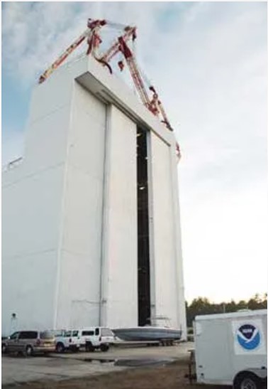
The HIF includes a 100-foot tall, 5.0-inch diameter stainless steel standpipe inside the former rocket hangar (talk about really BIG garage doors!!). Two stainless steel mixing tanks at the top level were used to prepare spike solutions of either volatile organic compounds (VOCs) or several cations. The standpipe is equipped with sampling ports at various depths that are accessible from one of the six floors in the building. The pumps were installed sequentially at 17 ft, 35 ft, and 76 ft below the top of casing, corresponding to three of the sampling ports on the standpipe. Two liters of water were purged through the pump at each level prior to sampling. Then a sample was collected simultaneously from the pump sample tube and from the port on the standpipe at the corresponding depth.
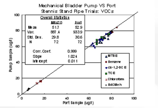
Results for VOC samples from the MB470 and corresponding port samples are plotted on the graph shown to the left. The results between the MB470 correlate well with the results from the port samples and lie close to the 1:1 line plotted on the graph. Some of the basic statistics for the paired data sets are shown on the graph. The correlation coefficient (r2) is 0.999 for the data set, and the regression line has a slope just greater than 1.0 and an intercept value of only 0.011. These results indicate that the mechanical bladder pump provides samples representative of water collected from a well.
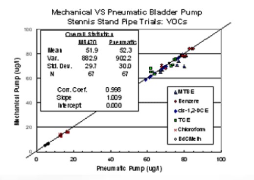
Another graph (right) shows how the MB470 compared to the small, 0.5-inch Geoprobe® Pneumatic Bladder Pump also included in this ETV verification program. Again, both the correlation coefficient and slope of the regression line are very close to 1.0 and the intercept is 0.00, nearly a perfect match.
So, what does all this mean? It means that the mechanical bladder pump will provide representative samples for the tested VOCs, essentially equivalent to those obtained with a pneumatic bladder pump, when the low-flow sampling protocol is followed.
Additional details of the ETV results for the verification study are available either by obtaining a copy of the formal EPA reports online at www.epa.gov (request document EPA/600/R-03/086 for the Mechanical Bladder Pump report or document EPA/600/R-03/085 for the Pneumatic Bladder Pump report). Geoprobe Systems® can provide you with a copy of the ETV Programs Verification Statement for either of the bladder pumps, and also has additional information on the use and specifications of both pumps.
(This article was featured in the Fall 2003 edition of the Probing Times)
Contact Us
1835 Wall Street
Salina, Kansas 67401
Phone: (785) 825-1842
Photo Gallery
Wes McCall
MB6000
MB470
Tyndall AFB
Mechanical Bladder Pump
Mechanical Bladder Pump2