
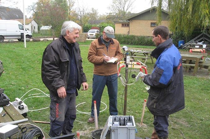
Pneumatic slug testing in glacial outwash deposits in Skudelev, Denmark. Slug tests were run at multiple depths to assess vertical variations in the formation hydraulic conductivity.
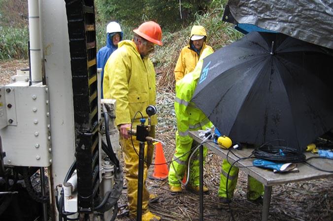
Pneumatic slug testing on a rainy day at Grassy Island in the Detroit River.
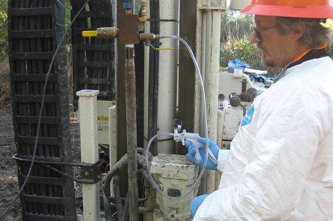
Using a hand pump to apply pressure or vacuum to the SP16 groundwater sampler to perform rising and falling head tests to assess formation permeability.
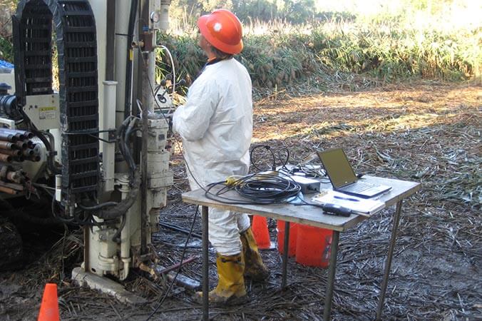
The data acquisition module for the hydraulic conductivity test is now connected to the laptop computer by USB and well responses is plotted onscreen as testing is performed.
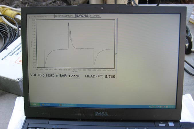
Onscreen plotting of well head responses with the Acquisition software as tests are performed. This displays a rising head tests recovery curve, pressurization peak and second rising head test as the data is acquired and save to the file.
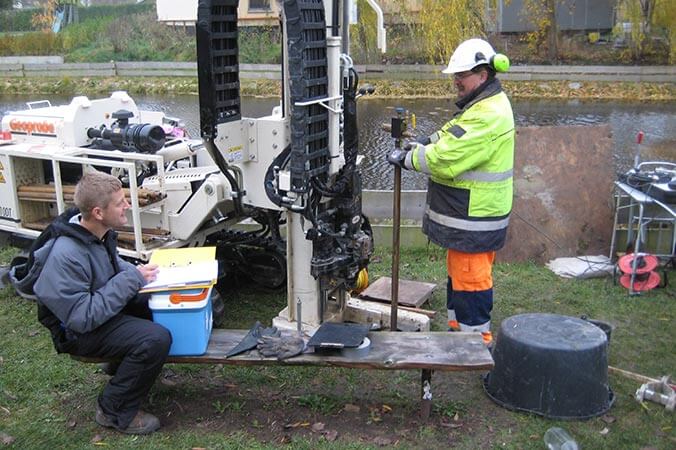
Conducting pneumatic slug testing with a screen point 16 groundwater piezometer in Skudelev, Denmark.
Conduct a hydraulic conductivity test to calculate Hydraulic Conductivity (K) of the subsurface formation by applying air pressure in a well and then releasing that pressure and monitoring the water level recovery.
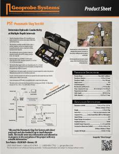
Geoprobe Systems® developed the GW1600 Pneumatic Slug Test Kit for use with Geoprobe® brand groundwater sampling, profiling, and monitoring tools to conduct pneumatic slug tests in saturated formations of unconsolidated soils or sediments. The hydraulic conductivity test system provides high-quality data for accurate determination of formation hydraulic conductivity (K). This is an important parameter in contaminant investigations as hydraulic conductivity is useful in determining the volume of water passing through a given soil cross section, and for estimating contaminant flux. This information can then be used to determine potential “risk” as well as guiding the design or implementation of remedial systems, whether that be injection of fluids, pump and treat or other remedial methods.
= Tool String Diagram (TSD)
System Overview
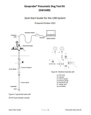
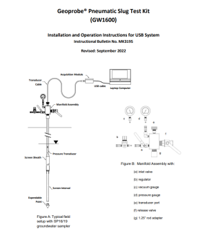
Geoprobe Systems® developed the GW1600 Pneumatic Slug Test Kit for use with Geoprobe® brand groundwater sampling, profiling, and monitoring tools to conduct pneumatic slug tests in saturated formations of unconsolidated soils or sediments. Adapters also permit use of the PST system on conventional PVC monitoring wells. The hydraulic conductivity test system provides high-quality data for accurate determination of formation hydraulic conductivity (K). The slug test kit is self-contained and is easily taken from location to location. In pneumatic slug testing, the well head is sealed and air pressure or vacuum is used to change the static water level. As air pressure in the well is increased or decreased, the water level changes until the water pressure "up" and the air pressure "down" are equal. Once the water level is stable, a release valve is quickly opened, instantaneously releasing the air pressure or vacuum. The water level recovers without splashing and the pressure transducer and data logger/computer record the changes in water level and time (Figure 2).
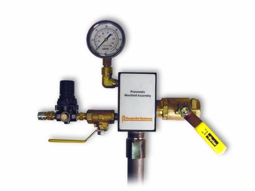
The hydraulic conductivity test kit includes the necessary adapters and manifold (Figure 1) you will need for slug testing in screens installed with Geoprobe® 1.25, 1.5, 1.75 in. rods. Adapters for use with 0.5in. - 2.0in. (12.7 to 50.8mm) diameter PVC monitoring wells are also available. Hydraulic conductivity (K) is an important parameter in contaminant investigations. Hydraulic conductivity (K) is useful in determining the volume of water passing through a given soil cross section, and for estimating contaminant flux. With the GW1600 Pneumatic Slug Test Kit, set-up is simple, requires only a few minutes, and all of the hydraulic conductivity test equipment needed is easily transported from one location to another.
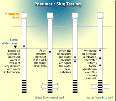
Figure 2:
Diagram of Rising Head Hydraulic Conductivity Test
Performing a Slug Test
Field Setup and Slug Test for Groundwater Sampler or Direct Push Monitoring Well
- The Slug Test Manifold is threaded onto the top of the rods or installed with an adapter on well casing. Either an O-ring or Teflon® tape is used to seal the surface connection and at each joint.
- The pressure transducer is lowered through the rod bore so it is below the static water level a known distance. The transducer must be placed so that when the water level is depressed with air pressure the transducer is always below the water.
- The airtight fitting on the transducer cable is tightened by hand to seal the connection.
- Transducer cable is attached to the data logger.
- The data logger is attached to a 115 volt power supply. A power inverter from a vehicle 12V outlet is sufficient.
- The logger's data cable is attached to the computer RS232 port for data transmission.
- Power on the field computer and start the Slug Test Data Acquisition Software.
- Close the release valve and the pressure regulator while opening the inlet valve.
- An air supply (pump or compressed air cylinder) is attached to the quick connect at the pressure regulator.
- The pressure regulator is slowly opened to pressurize the well head and depress water level the selected distance. Usually less than 2 psi of air pressure is required.
- Close inlet valve and leak check the system.
- Monitor transducer response on computer screen and air pressure on gauge to verify system is stable.
- Quickly open the release valve to initiate the slug test.
- Allow sufficient time for water level to recover to static level. The slug test is now complete.
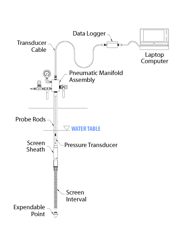
Figure 3:
Slug Test Setup with a Screen Point 16 Groundwater Sampler
Figure 4 shows what is happening in the well during a rising head slug test.

Figure 4:
Diagram of a Rising Head Hydraulic Conductivity Test
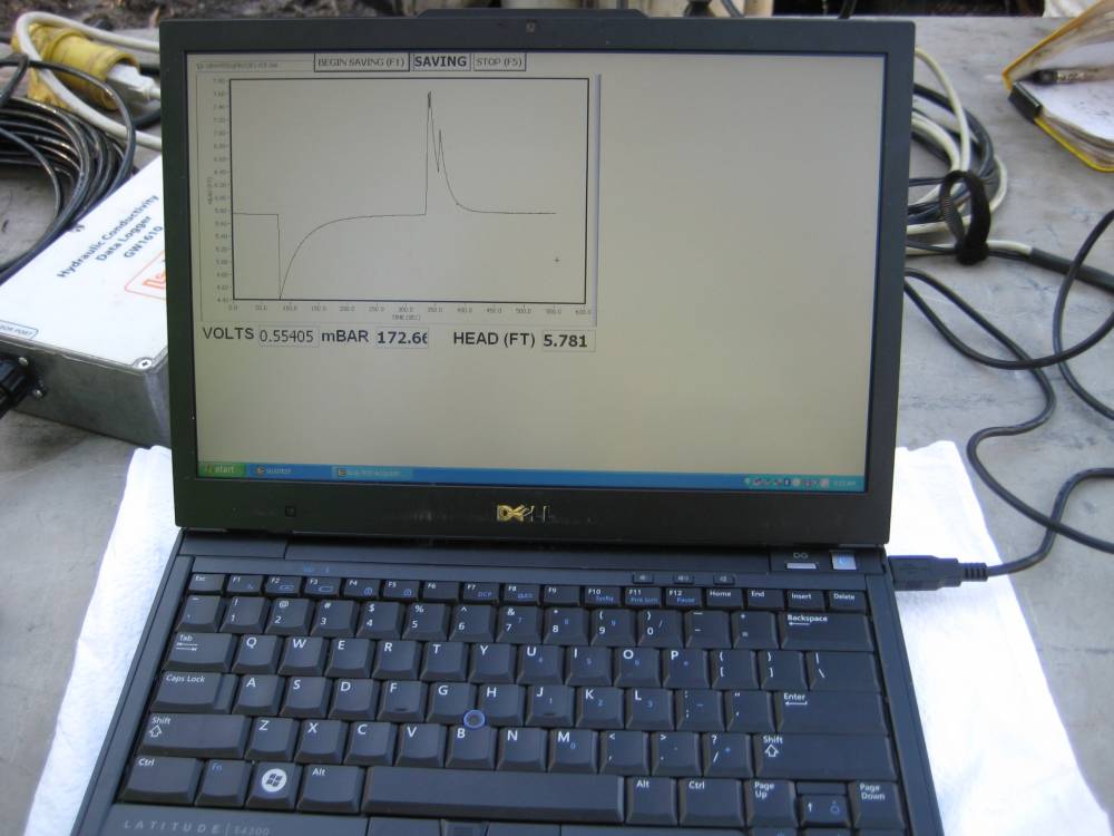
Figure 4:
Acquiring a Slug Test Data in the Field
Analyzing the Data
This figure shows data obtained in a moderate K formation using a pneumatic slug test technique. This hydraulic conductivity test data, taken in glacial soil in northern Illinois, shows a single test cycle of pressurization followed by a release of air pressure and recovery (formation response).
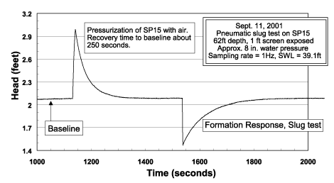
Figure 4:
SP15 Slug Test Moderate-K Formation
Applications
Assembly and Driving
The SP16 sampler is assembled with fresh O-rings to provide a sealed system while advancing the tool string. An O-ring kit is available for these tools and details of assembly are provided in the standard operating procedure (link below). After each rod is driven, an O-ring is placed on the rod before the next rod is added. All rod joints must be sealed to prevent air leaks and allow for pneumatic slug testing. Additional probe rods are added to the tool string and driven until the end of the screen is at the desired depth.
Deployment
Once the screen is at the desired depth, extension rods with a screen push adapter (GW1535) are inserted through the bore of the rods. While holding down on the extension rod handle, the probe rods and screen sheath are retracted with the rod grip system to expose the screen to the formation. Knowing the exact length of screen exposed to the formation is critical for calculating the hydraulic conductivity (K). Determine beforehand the length of screen to be exposed and mark this on the extension rod above the top probe rod. Be sure to add 2 inches to the screen length to account for the shaft of the expendable drive point and blank section at base of screen (Figure 4).
Screen Development
Development is a key step required to make an accurate determination of the hydraulic conductivity (K) of the screened formation. Development is needed to reestablish natural flow from the formation into the screen (ASTM 5521). Even in “clean” sand aquifers, conducting a slug test before development routinely yield determinations of hydraulic conductivity (K) 3 to 5 times less than slug tests after development (Butler et al. 2002). Development of the SP16 in sandy formations may be completed using the tubing check valve system (MN 214061). Oscillating and purging through the screen interval with the check valve is effective.
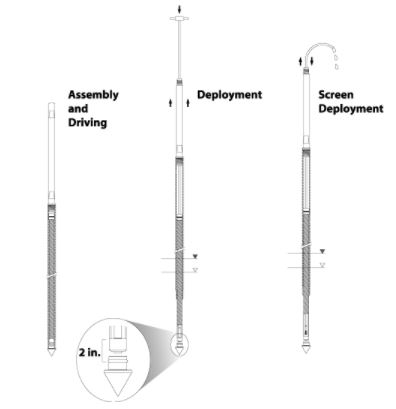
Figure 5:
SP16 Screen Deployment for Groundwater Sampling and Pneumatic Slug testing
Slug Testing Fine Grained Formations
So you need to conduct a slug test in a fine-grained formation. Yet you know driving the SP16 groundwater samplers or advancing the DT22 rod system into the formation will cause compression and bias your hydraulic conductivity test results. Your best option... drive the 2.25 in. dual tube rods down to the top of the interval you want to slug test. Retract the inner 1 in. rods and attach the Soil Precore Drive head and sample tube. Lower the sampler to depth and core the soil below the SP22 Profiler screen. You may want to "brush" the cored formation before installing the screen with the BU600 brush to relieve smearing. Now you are ready to slug test in the fine grained low-K formation. A simple falling head test is most often used under these conditions.
Do You Know Your "K"?
Hydraulic Conductivity (K) is a measure of the capability of a medium to transmit water.
This is an important parameter in contaminant investigations as hydraulic conductivity is useful in determining the volume of water passing through a given soil cross section, and for estimating the flow velocity of contaminated groundwater.
In the past, hydraulic conductivity was typically measured using pumping tests or by performing “slug tests” of installed wells. Both of these past hydraulic conductivity test practices, while having their technical strengths, required the installation of some form of well casing; either of the pumping or monitoring type.
Simulated transducer data during a slug test (well head pressurized, stabilization, and release of pressure to initiate the slug test response).
What is a slug test?
As defined by Fetter (1994) a slug test is “an aquifer test made by pouring a small instantaneous charge of water into a well or by withdrawing a slug of water from the well” (e.g with a bailer). This definition clearly shows how early slug testing was conducted, by quickly adding water to a well or quickly removing a bailer full of water from the well.
When environmental monitoring wells are being tested, you don’t want to add (or remove) water from the well. This either alters the ambient water quality or generates potentially hazardous waste. It quickly became common for people to use a “mechanical slug” to run a slug test. This is simply a 3 to 5 foot long section of PVC pipe filled with sand and capped on each end. A cord is attached to one end of the mechanical slug so it can be quickly lowered below the water level (slug-in test/falling head test) and then later quickly raised above the water level (slug-out test/rising head test). Again the change in water level and time are recorded.
Quickly lowering or raising the mechanical slug in or out of the water may cause splashing in the well. For slug tests lasting several minutes or longer this is not a significant problem. However, for wells that recover from a slug test in less than a minute the splashing will interfere with a lot of the early time data so that a good determination of the changes in the water level can not be made. Because of these problems the pneumatic slug testing method was developed (Prosser 1981, Butler 1997). In this method, the well head is sealed and air pressure is used to displace the water level.

Pneumatic Slug Testing
Why calculate the hydraulic conductivity of a formation?
Since the hydraulic conductivity lets you know how fast the groundwater can move through a formation, it is the first step in knowing how fast contaminants may be able to move. This information is used to determine the potential “risk” caused by the presence and migration of contaminants in the subsurface for risk based corrective actions (RBCA). It is also a vital piece of information required to determine if monitored natural attenuation (MNA) is an acceptable remedial option for a contaminated facility (EPA 1998). Additionally, knowing the hydraulic conductivity is a very useful piece of information when implementing or designing a remedial system, be it injection of fluids, pump and treat, or other remedial methods.
Why use Direct Push methods to conduct slug tests?
There are several reasons, but primarily economics is the driver. You can save thousands of dollars and a lot of time using direct push methods to do this work. A summary of specific reasons include:
- Installation of permanent monitoring wells is not required. This eliminates the need for drilling, disposal of drill cuttings, cost of well construction, and generation of large volumes of development water.
- Hydraulic conductivity tests can be conducted at multiple depths and at several locations across the site in a timely manner to determine vertical and horizontal variations in K.
- High-quality depth discrete data on hydraulic conductivity can be obtained in many unconsolidated formations.
- Equipment and methods exist for measurement of hydraulic conductivity in formations ranging from very high-K (> 750ft/day, 2.6 x 10⁻¹ cm/sec.) to very low-K (< 0.003 ft/day, 1 x 10⁻⁶ cm/sec) materials.
- U.S. EPA recommends use of direct push methods for determining vertical and lateral variations in K so that contaminant migration pathways can be located and assessed. (Monitored Natural Attenuation for Ground Water, EPA/625/K-98/001).
- This information is needed for RBCA and MNA investigations and remedial actions.
- Knowledge of vertical and lateral changes in K can be used to optimize remediation design and minimize the potential for having to re-engineer a poorly planned remedial design.
- The same tool (e.g. SP16 or Profiler) can be used repeatedly after decontamination to conduct slug tests which reduces equipment costs.
- Minimal contaminated waste is generated (essentially no waste cuttings) and exposure hazards to workers are reduced.
- You can provide a new and valuable service to your clients while saving them money and time to get information they need.
Can direct push slug tests provide results comparable to tests conducted in conventional monitoring wells?
In short, YES. When the screens are installed properly and adequately developed, field comparison has shown that the direct push methods provide essentially the same results as conventional monitoring wells screened over the same interval (Butler et al. 2002, McCall et al., 2002).
Where did the slug come from?
Slug Test. No, it’s not a test to see if you have slimy worms crawling around in your garden! When single well hydraulic conductivity tests first got started, the wells being tested were pretty large in diameter ... 4-in., 8-in. or even larger. There were no neat small pressure transducers, no data loggers, and definitely no portable computers at this time. The tests were completed by pouring a 5-gallon bucket of water down the well casing and measuring the change in water level with a tape, marking time using your wrist watch, and writing down the time and water level in your field book with your No. 2 lead pencil! The 5-gallons of water was simply a big “slug” of water poured down the well. And presto! The “Slug Test” was born.
Features & Options
Figure 1: Slug Test Wellhead Manifold
Geoprobe Systems® developed the GW1600 Pneumatic Slug Test Kit for use with Geoprobe® brand groundwater sampling, profiling, and monitoring tools to conduct pneumatic slug tests in saturated formations of unconsolidated soils or sediments. Adapters also permit use of the PST system on conventional PVC monitoring wells. The hydraulic conductivity test system provides high-quality data for accurate determination of formation hydraulic conductivity (K). The slug test kit is self-contained and is easily taken from location to location. In pneumatic slug testing, the well head is sealed and air pressure or vacuum is used to change the static water level. As air pressure in the well is increased or decreased, the water level changes until the water pressure "up" and the air pressure "down" are equal. Once the water level is stable, a release valve is quickly opened, instantaneously releasing the air pressure or vacuum. The water level recovers without splashing and the pressure transducer and data logger/computer record the changes in water level and time (Figure 2).
The hydraulic conductivity test kit includes the necessary adapters and manifold (Figure 1) you will need for slug testing in screens installed with Geoprobe® 1.25, 1.5, 1.75 in. rods. Adapters for use with 0.5in. - 2.0in. (12.7 to 50.8mm) diameter PVC monitoring wells are also available. Hydraulic conductivity (K) is an important parameter in contaminant investigations. Hydraulic conductivity (K) is useful in determining the volume of water passing through a given soil cross section, and for estimating contaminant flux. With the GW1600 Pneumatic Slug Test Kit, set-up is simple, requires only a few minutes, and all of the hydraulic conductivity test equipment needed is easily transported from one location to another.
Figure 2:
Diagram of Rising Head Hydraulic Conductivity Test
Field Setup and Slug Test for Groundwater Sampler or Direct Push Monitoring Well
- The Slug Test Manifold is threaded onto the top of the rods or installed with an adapter on well casing. Either an O-ring or Teflon® tape is used to seal the surface connection and at each joint.
- The pressure transducer is lowered through the rod bore so it is below the static water level a known distance. The transducer must be placed so that when the water level is depressed with air pressure the transducer is always below the water.
- The airtight fitting on the transducer cable is tightened by hand to seal the connection.
- Transducer cable is attached to the data logger.
- The data logger is attached to a 115 volt power supply. A power inverter from a vehicle 12V outlet is sufficient.
- The logger's data cable is attached to the computer RS232 port for data transmission.
- Power on the field computer and start the Slug Test Data Acquisition Software.
- Close the release valve and the pressure regulator while opening the inlet valve.
- An air supply (pump or compressed air cylinder) is attached to the quick connect at the pressure regulator.
- The pressure regulator is slowly opened to pressurize the well head and depress water level the selected distance. Usually less than 2 psi of air pressure is required.
- Close inlet valve and leak check the system.
- Monitor transducer response on computer screen and air pressure on gauge to verify system is stable.
- Quickly open the release valve to initiate the slug test.
- Allow sufficient time for water level to recover to static level. The slug test is now complete.
Figure 3:
Slug Test Setup with a Screen Point 16 Groundwater Sampler
Figure 4 shows what is happening in the well during a rising head slug test.
Figure 4:
Diagram of a Rising Head Hydraulic Conductivity Test
Figure 4:
Acquiring a Slug Test Data in the Field
This figure shows data obtained in a moderate K formation using a pneumatic slug test technique. This hydraulic conductivity test data, taken in glacial soil in northern Illinois, shows a single test cycle of pressurization followed by a release of air pressure and recovery (formation response).
Figure 4:
SP15 Slug Test Moderate-K Formation
Assembly and Driving
The SP16 sampler is assembled with fresh O-rings to provide a sealed system while advancing the tool string. An O-ring kit is available for these tools and details of assembly are provided in the standard operating procedure (link below). After each rod is driven, an O-ring is placed on the rod before the next rod is added. All rod joints must be sealed to prevent air leaks and allow for pneumatic slug testing. Additional probe rods are added to the tool string and driven until the end of the screen is at the desired depth.
Deployment
Once the screen is at the desired depth, extension rods with a screen push adapter (GW1535) are inserted through the bore of the rods. While holding down on the extension rod handle, the probe rods and screen sheath are retracted with the rod grip system to expose the screen to the formation. Knowing the exact length of screen exposed to the formation is critical for calculating the hydraulic conductivity (K). Determine beforehand the length of screen to be exposed and mark this on the extension rod above the top probe rod. Be sure to add 2 inches to the screen length to account for the shaft of the expendable drive point and blank section at base of screen (Figure 4).
Screen Development
Development is a key step required to make an accurate determination of the hydraulic conductivity (K) of the screened formation. Development is needed to reestablish natural flow from the formation into the screen (ASTM 5521). Even in “clean” sand aquifers, conducting a slug test before development routinely yield determinations of hydraulic conductivity (K) 3 to 5 times less than slug tests after development (Butler et al. 2002). Development of the SP16 in sandy formations may be completed using the tubing check valve system (MN 214061). Oscillating and purging through the screen interval with the check valve is effective.
Figure 5:
SP16 Screen Deployment for Groundwater Sampling and Pneumatic Slug testing
Slug Testing Fine Grained Formations
So you need to conduct a slug test in a fine-grained formation. Yet you know driving the SP16 groundwater samplers or advancing the DT22 rod system into the formation will cause compression and bias your hydraulic conductivity test results. Your best option... drive the 2.25 in. dual tube rods down to the top of the interval you want to slug test. Retract the inner 1 in. rods and attach the Soil Precore Drive head and sample tube. Lower the sampler to depth and core the soil below the SP22 Profiler screen. You may want to "brush" the cored formation before installing the screen with the BU600 brush to relieve smearing. Now you are ready to slug test in the fine grained low-K formation. A simple falling head test is most often used under these conditions.
Hydraulic Conductivity (K) is a measure of the capability of a medium to transmit water.
This is an important parameter in contaminant investigations as hydraulic conductivity is useful in determining the volume of water passing through a given soil cross section, and for estimating the flow velocity of contaminated groundwater.
In the past, hydraulic conductivity was typically measured using pumping tests or by performing “slug tests” of installed wells. Both of these past hydraulic conductivity test practices, while having their technical strengths, required the installation of some form of well casing; either of the pumping or monitoring type.
Simulated transducer data during a slug test (well head pressurized, stabilization, and release of pressure to initiate the slug test response).
What is a slug test?
As defined by Fetter (1994) a slug test is “an aquifer test made by pouring a small instantaneous charge of water into a well or by withdrawing a slug of water from the well” (e.g with a bailer). This definition clearly shows how early slug testing was conducted, by quickly adding water to a well or quickly removing a bailer full of water from the well.
When environmental monitoring wells are being tested, you don’t want to add (or remove) water from the well. This either alters the ambient water quality or generates potentially hazardous waste. It quickly became common for people to use a “mechanical slug” to run a slug test. This is simply a 3 to 5 foot long section of PVC pipe filled with sand and capped on each end. A cord is attached to one end of the mechanical slug so it can be quickly lowered below the water level (slug-in test/falling head test) and then later quickly raised above the water level (slug-out test/rising head test). Again the change in water level and time are recorded.
Quickly lowering or raising the mechanical slug in or out of the water may cause splashing in the well. For slug tests lasting several minutes or longer this is not a significant problem. However, for wells that recover from a slug test in less than a minute the splashing will interfere with a lot of the early time data so that a good determination of the changes in the water level can not be made. Because of these problems the pneumatic slug testing method was developed (Prosser 1981, Butler 1997). In this method, the well head is sealed and air pressure is used to displace the water level.
Pneumatic Slug Testing
Why calculate the hydraulic conductivity of a formation?
Since the hydraulic conductivity lets you know how fast the groundwater can move through a formation, it is the first step in knowing how fast contaminants may be able to move. This information is used to determine the potential “risk” caused by the presence and migration of contaminants in the subsurface for risk based corrective actions (RBCA). It is also a vital piece of information required to determine if monitored natural attenuation (MNA) is an acceptable remedial option for a contaminated facility (EPA 1998). Additionally, knowing the hydraulic conductivity is a very useful piece of information when implementing or designing a remedial system, be it injection of fluids, pump and treat, or other remedial methods.
Why use Direct Push methods to conduct slug tests?
There are several reasons, but primarily economics is the driver. You can save thousands of dollars and a lot of time using direct push methods to do this work. A summary of specific reasons include:
- Installation of permanent monitoring wells is not required. This eliminates the need for drilling, disposal of drill cuttings, cost of well construction, and generation of large volumes of development water.
- Hydraulic conductivity tests can be conducted at multiple depths and at several locations across the site in a timely manner to determine vertical and horizontal variations in K.
- High-quality depth discrete data on hydraulic conductivity can be obtained in many unconsolidated formations.
- Equipment and methods exist for measurement of hydraulic conductivity in formations ranging from very high-K (> 750ft/day, 2.6 x 10⁻¹ cm/sec.) to very low-K (< 0.003 ft/day, 1 x 10⁻⁶ cm/sec) materials.
- U.S. EPA recommends use of direct push methods for determining vertical and lateral variations in K so that contaminant migration pathways can be located and assessed. (Monitored Natural Attenuation for Ground Water, EPA/625/K-98/001).
- This information is needed for RBCA and MNA investigations and remedial actions.
- Knowledge of vertical and lateral changes in K can be used to optimize remediation design and minimize the potential for having to re-engineer a poorly planned remedial design.
- The same tool (e.g. SP16 or Profiler) can be used repeatedly after decontamination to conduct slug tests which reduces equipment costs.
- Minimal contaminated waste is generated (essentially no waste cuttings) and exposure hazards to workers are reduced.
- You can provide a new and valuable service to your clients while saving them money and time to get information they need.
Can direct push slug tests provide results comparable to tests conducted in conventional monitoring wells?
In short, YES. When the screens are installed properly and adequately developed, field comparison has shown that the direct push methods provide essentially the same results as conventional monitoring wells screened over the same interval (Butler et al. 2002, McCall et al., 2002).
Where did the slug come from?
Slug Test. No, it’s not a test to see if you have slimy worms crawling around in your garden! When single well hydraulic conductivity tests first got started, the wells being tested were pretty large in diameter ... 4-in., 8-in. or even larger. There were no neat small pressure transducers, no data loggers, and definitely no portable computers at this time. The tests were completed by pouring a 5-gallon bucket of water down the well casing and measuring the change in water level with a tape, marking time using your wrist watch, and writing down the time and water level in your field book with your No. 2 lead pencil! The 5-gallons of water was simply a big “slug” of water poured down the well. And presto! The “Slug Test” was born.
Tooling & Instrumentation
The kit includes everything you will need for slug testing in screens installed with Geoprobe® 1.25 or 1.5 in. rods. Kit includes the pneumatic manifold, gauges, rod adapters, pressure transducer, a hand pump for applying air pressure or vacuum to the well head, data logger that adapts to the user's PC along with the Aquisition software.
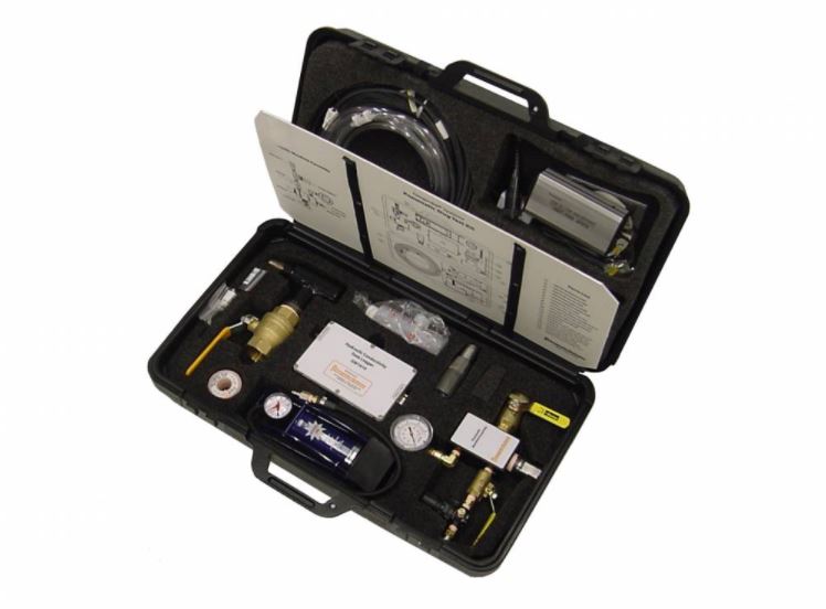
Figure 5:
Slug Test Kit
With the Pneumatic Slug Test Kit (MN 214038), set-up is simple, requires only a few minutes, all of the essential assemblies and accessories are included to prepare you for measuring hydraulic conductivity with Geoprobe® groundwater samplers in the field. The kit is self contained and is easy to move from location to location. Optional PVC adapters allow for pneumatic slug testing on PVC monitoring wells from 0.5in. to 2.0in. nominal diameter.
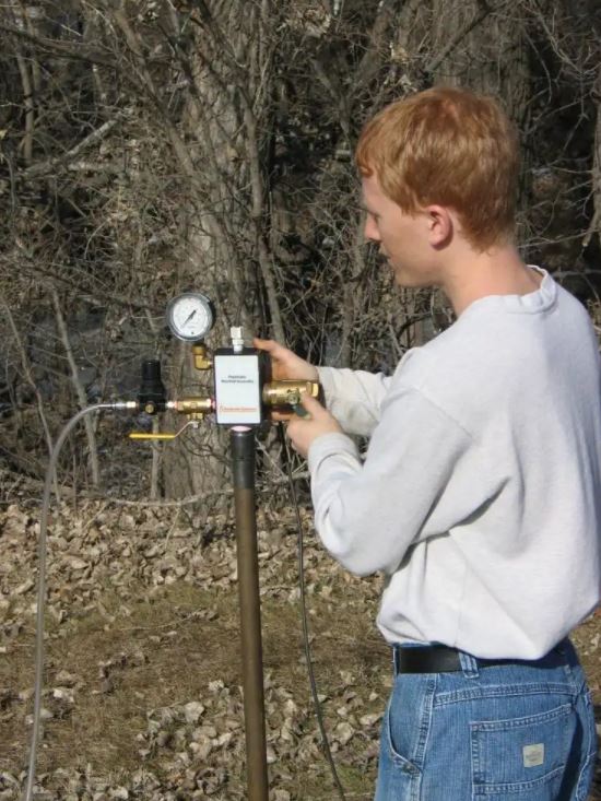
Figure 6:
Setting up for a slug test
Other features of the system include:
- Revised Slug Test Acquisition Software (CD) is installed on your laptop computer for real-time observation of field tests and for data storage.
- The pneumatic manifold assembly includes valves, a pressure regulator, pressure and vacuum gauges necessary to quickly and easily conduct pneumatic slug tests.
- The kit includes adapters for performing slug tests in Geoprobe® 1.25, 1.5, and 1.75 in. probe rods.
- The small diameter pressure transducer allows for slug tests in probe rods and PVC casing as small as 0.5 in. (12.7 mm) ID.
- The Slug Test Data Aquisition Module enables use of sampling rates of 1, 2, 5 and 10 Hertz to meet requirements for low-K formations and high-K formations producing oscillatory responses.
- A simple hand pump supplies air pressure or vacuum as required to conduct the pneumatic tests in small direct push tools.
- A power inverter (included in the kit) lets you operate the entire system from your vehicle's auxiliary power outlet or power point.
- The data aquisition module connects by USB to your laptop computer for data transfer and power supply.
- The acquisition software provides live-time viewing of slug test responses as testing is conducted in the field. Multiple tests may be performed to assess repeatability and data quality.
- Because of the small diameter of many DP groundwater tools, minimal development water is generated, often less than 2 to 3 gallons (8 to 12L).
- The entire system can be stored and transported in its carrying case which measures 27.5 in. x 16 in. x 7 in. (699 x 406 x 178 mm) and weighs about 29.8 lb (13.5 Kg).
- Optional adapters are available to conduct pneumatic slug tests in PVC casing from nominal 0.5- to 2.0 in. (12.7 to 50.8 mm) diameter.
Resources
Click on a section below to view information.
Depend on Team Geoprobe®
Since 1987, Geoprobe® has manufactured innovative drilling rigs and tooling - engineered for efficiency and safety - simplifying drillers’ jobs and empowering their companies to succeed as productive and profitable leaders in the industry. When you partner with Geoprobe® you receive:
Customer-inspired Innovation
Engineering and building industry-leading drilling rigs, tooling, and techniques for the technical driller based on your needs to work safer and more efficiently.
Exceptional Value
Ensuring drilling rigs and tooling are created in conjunction – with consistent quality – to collect the highest-quality information with the most accurate result to get you to, into, and through the job efficiently.
Superior Service
Equipping you to do your best job and keeping you in the field via one-on-one expert sales and service technicians manning live support phone lines, shipping necessary parts same-day.
Geoprobe Systems® developed the GW1600 Pneumatic Slug Test Kit for use with Geoprobe® brand groundwater sampling, profiling, and monitoring tools to conduct pneumatic slug tests in saturated formations of unconsolidated soils or sediments. Adapters also permit use of the PST system on conventional PVC monitoring wells. The hydraulic conductivity test system provides high-quality data for accurate determination of formation hydraulic conductivity (K). The slug test kit is self-contained and is easily taken from location to location. In pneumatic slug testing, the well head is sealed and air pressure or vacuum is used to change the static water level. As air pressure in the well is increased or decreased, the water level changes until the water pressure "up" and the air pressure "down" are equal. Once the water level is stable, a release valve is quickly opened, instantaneously releasing the air pressure or vacuum. The water level recovers without splashing and the pressure transducer and data logger/computer record the changes in water level and time (Figure 2).
The hydraulic conductivity test kit includes the necessary adapters and manifold (Figure 1) you will need for slug testing in screens installed with Geoprobe® 1.25, 1.5, 1.75 in. rods. Adapters for use with 0.5in. - 2.0in. (12.7 to 50.8mm) diameter PVC monitoring wells are also available. Hydraulic conductivity (K) is an important parameter in contaminant investigations. Hydraulic conductivity (K) is useful in determining the volume of water passing through a given soil cross section, and for estimating contaminant flux. With the GW1600 Pneumatic Slug Test Kit, set-up is simple, requires only a few minutes, and all of the hydraulic conductivity test equipment needed is easily transported from one location to another.
Figure 2: Diagram of Rising Head Hydraulic Conductivity Test
:
:
:
Field Setup and Slug Test for Groundwater Sampler or Direct Push Monitoring Well
- The Slug Test Manifold is threaded onto the top of the rods or installed with an adapter on well casing. Either an O-ring or Teflon® tape is used to seal the surface connection and at each joint.
- The pressure transducer is lowered through the rod bore so it is below the static water level a known distance. The transducer must be placed so that when the water level is depressed with air pressure the transducer is always below the water.
- The airtight fitting on the transducer cable is tightened by hand to seal the connection.
- Transducer cable is attached to the data logger.
- The data logger is attached to a 115 volt power supply. A power inverter from a vehicle 12V outlet is sufficient.
- The logger's data cable is attached to the computer RS232 port for data transmission.
- Power on the field computer and start the Slug Test Data Acquisition Software.
- Close the release valve and the pressure regulator while opening the inlet valve.
- An air supply (pump or compressed air cylinder) is attached to the quick connect at the pressure regulator.
- The pressure regulator is slowly opened to pressurize the well head and depress water level the selected distance. Usually less than 2 psi of air pressure is required.
- Close inlet valve and leak check the system.
- Monitor transducer response on computer screen and air pressure on gauge to verify system is stable.
- Quickly open the release valve to initiate the slug test.
- Allow sufficient time for water level to recover to static level. The slug test is now complete.
Figure 3: Slug Test Setup with a Screen Point 16 Groundwater Sampler
Figure 4 shows what is happening in the well during a rising head slug test.
Figure 4: Diagram of a Rising Head Hydraulic Conductivity Test
Figure 4: Acquiring a Slug Test Data in the Field
:
This figure shows data obtained in a moderate K formation using a pneumatic slug test technique. This hydraulic conductivity test data, taken in glacial soil in northern Illinois, shows a single test cycle of pressurization followed by a release of air pressure and recovery (formation response).
Figure 4: SP15 Slug Test Moderate-K Formation
:
:
:
Assembly and Driving
The SP16 sampler is assembled with fresh O-rings to provide a sealed system while advancing the tool string. An O-ring kit is available for these tools and details of assembly are provided in the standard operating procedure (link below). After each rod is driven, an O-ring is placed on the rod before the next rod is added. All rod joints must be sealed to prevent air leaks and allow for pneumatic slug testing. Additional probe rods are added to the tool string and driven until the end of the screen is at the desired depth.
Deployment
Once the screen is at the desired depth, extension rods with a screen push adapter (GW1535) are inserted through the bore of the rods. While holding down on the extension rod handle, the probe rods and screen sheath are retracted with the rod grip system to expose the screen to the formation. Knowing the exact length of screen exposed to the formation is critical for calculating the hydraulic conductivity (K). Determine beforehand the length of screen to be exposed and mark this on the extension rod above the top probe rod. Be sure to add 2 inches to the screen length to account for the shaft of the expendable drive point and blank section at base of screen (Figure 4).
Screen Development
Development is a key step required to make an accurate determination of the hydraulic conductivity (K) of the screened formation. Development is needed to reestablish natural flow from the formation into the screen (ASTM 5521). Even in “clean” sand aquifers, conducting a slug test before development routinely yield determinations of hydraulic conductivity (K) 3 to 5 times less than slug tests after development (Butler et al. 2002). Development of the SP16 in sandy formations may be completed using the tubing check valve system (MN 214061). Oscillating and purging through the screen interval with the check valve is effective.
Figure 5: SP16 Screen Deployment for Groundwater Sampling and Pneumatic Slug testing
Slug Testing Fine Grained Formations
So you need to conduct a slug test in a fine-grained formation. Yet you know driving the SP16 groundwater samplers or advancing the DT22 rod system into the formation will cause compression and bias your hydraulic conductivity test results. Your best option... drive the 2.25 in. dual tube rods down to the top of the interval you want to slug test. Retract the inner 1 in. rods and attach the Soil Precore Drive head and sample tube. Lower the sampler to depth and core the soil below the SP22 Profiler screen. You may want to "brush" the cored formation before installing the screen with the BU600 brush to relieve smearing. Now you are ready to slug test in the fine grained low-K formation. A simple falling head test is most often used under these conditions.
:
:
:
Hydraulic Conductivity (K) is a measure of the capability of a medium to transmit water.
This is an important parameter in contaminant investigations as hydraulic conductivity is useful in determining the volume of water passing through a given soil cross section, and for estimating the flow velocity of contaminated groundwater.
In the past, hydraulic conductivity was typically measured using pumping tests or by performing “slug tests” of installed wells. Both of these past hydraulic conductivity test practices, while having their technical strengths, required the installation of some form of well casing; either of the pumping or monitoring type.
: Simulated transducer data during a slug test (well head pressurized, stabilization, and release of pressure to initiate the slug test response).
What is a slug test?
As defined by Fetter (1994) a slug test is “an aquifer test made by pouring a small instantaneous charge of water into a well or by withdrawing a slug of water from the well” (e.g with a bailer). This definition clearly shows how early slug testing was conducted, by quickly adding water to a well or quickly removing a bailer full of water from the well.
When environmental monitoring wells are being tested, you don’t want to add (or remove) water from the well. This either alters the ambient water quality or generates potentially hazardous waste. It quickly became common for people to use a “mechanical slug” to run a slug test. This is simply a 3 to 5 foot long section of PVC pipe filled with sand and capped on each end. A cord is attached to one end of the mechanical slug so it can be quickly lowered below the water level (slug-in test/falling head test) and then later quickly raised above the water level (slug-out test/rising head test). Again the change in water level and time are recorded.
Quickly lowering or raising the mechanical slug in or out of the water may cause splashing in the well. For slug tests lasting several minutes or longer this is not a significant problem. However, for wells that recover from a slug test in less than a minute the splashing will interfere with a lot of the early time data so that a good determination of the changes in the water level can not be made. Because of these problems the pneumatic slug testing method was developed (Prosser 1981, Butler 1997). In this method, the well head is sealed and air pressure is used to displace the water level.
: Pneumatic Slug Testing
Why calculate the hydraulic conductivity of a formation?
Since the hydraulic conductivity lets you know how fast the groundwater can move through a formation, it is the first step in knowing how fast contaminants may be able to move. This information is used to determine the potential “risk” caused by the presence and migration of contaminants in the subsurface for risk based corrective actions (RBCA). It is also a vital piece of information required to determine if monitored natural attenuation (MNA) is an acceptable remedial option for a contaminated facility (EPA 1998). Additionally, knowing the hydraulic conductivity is a very useful piece of information when implementing or designing a remedial system, be it injection of fluids, pump and treat, or other remedial methods.
Why use Direct Push methods to conduct slug tests?
There are several reasons, but primarily economics is the driver. You can save thousands of dollars and a lot of time using direct push methods to do this work. A summary of specific reasons include:
- Installation of permanent monitoring wells is not required. This eliminates the need for drilling, disposal of drill cuttings, cost of well construction, and generation of large volumes of development water.
- Hydraulic conductivity tests can be conducted at multiple depths and at several locations across the site in a timely manner to determine vertical and horizontal variations in K.
- High-quality depth discrete data on hydraulic conductivity can be obtained in many unconsolidated formations.
- Equipment and methods exist for measurement of hydraulic conductivity in formations ranging from very high-K (> 750ft/day, 2.6 x 10⁻¹ cm/sec.) to very low-K (< 0.003 ft/day, 1 x 10⁻⁶ cm/sec) materials.
- U.S. EPA recommends use of direct push methods for determining vertical and lateral variations in K so that contaminant migration pathways can be located and assessed. (Monitored Natural Attenuation for Ground Water, EPA/625/K-98/001).
- This information is needed for RBCA and MNA investigations and remedial actions.
- Knowledge of vertical and lateral changes in K can be used to optimize remediation design and minimize the potential for having to re-engineer a poorly planned remedial design.
- The same tool (e.g. SP16 or Profiler) can be used repeatedly after decontamination to conduct slug tests which reduces equipment costs.
- Minimal contaminated waste is generated (essentially no waste cuttings) and exposure hazards to workers are reduced.
- You can provide a new and valuable service to your clients while saving them money and time to get information they need.
Can direct push slug tests provide results comparable to tests conducted in conventional monitoring wells?
In short, YES. When the screens are installed properly and adequately developed, field comparison has shown that the direct push methods provide essentially the same results as conventional monitoring wells screened over the same interval (Butler et al. 2002, McCall et al., 2002).
Where did the slug come from?
Slug Test. No, it’s not a test to see if you have slimy worms crawling around in your garden! When single well hydraulic conductivity tests first got started, the wells being tested were pretty large in diameter ... 4-in., 8-in. or even larger. There were no neat small pressure transducers, no data loggers, and definitely no portable computers at this time. The tests were completed by pouring a 5-gallon bucket of water down the well casing and measuring the change in water level with a tape, marking time using your wrist watch, and writing down the time and water level in your field book with your No. 2 lead pencil! The 5-gallons of water was simply a big “slug” of water poured down the well. And presto! The “Slug Test” was born.
:
: